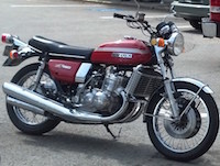
I just bought, and installed a VR3-SGT voltage regulator + R255a-SGT Rectifier on my '73 GT750 from Oregonmotorcycleparts.
If I set the voltage to 14.5v with the headlight on (above 2000rpm) it will drop to 14.1 when I turn the light off. If I turn on the high beam it will rise to 14.6 ish. The voltage seams to be dependent on the load? Isn't it the regulators job to keep the voltage steady?
The bike didn't have any apparent charging problems, I just didn't trust the old stuff. Battery is good. All of my electrical connections are clean too.
Oregon told me this "It's possible that the voltage feed to the orange wire isn't consistent. For a test you can jump power directly from the hot side of the battery to the orange wire at the regulator. This is only as a test since it would leave the bike powered up all the time.
I did and the voltage drops to 14.02, and with the high beam on its 14.26 which is much better.
Oregon replied "The problem is either in the ignition switch or some corroded connections somewhere...
Ignition switch was taken apart, and cleaned, and my connections look good, so where do I look now?
GT750 regulator problem?
Moderators: oldjapanesebikes, H2RICK, diamondj, Suzsmokeyallan
-
Blokhead

- On the main road
- Posts: 119
- Joined: Sat Jul 31, 2010 5:53 am
- Country: USA
- Suzuki 2-Strokes: GT750
- Location: Cleveland
GT750 regulator problem?
'79 KZ650SR w/162hp Polaris XC700 Snowmobile Engine Dragbike
'73 GT750
'74 H2 750
'90 GSXR 1100
'75 H1 500
'76 KH400
'76 RD400
Minitrail 50
2 Trizingers
'73 GT750
'74 H2 750
'90 GSXR 1100
'75 H1 500
'76 KH400
'76 RD400
Minitrail 50
2 Trizingers
-
jabcb
- Moto GP
- Posts: 4251
- Joined: Mon Dec 13, 2010 4:32 pm
- Country: USA
- Suzuki 2-Strokes: 69 T350 thru 75 GT750
- Location: southwestern Pennsylvania
Re: GT750 regulator problem?
Wiring diagrams are here: viewtopic.php?f=29&t=4743
Suzuki used fairly skimpy wires. The main hot wires are red from battery & rectifier to ignition switch, and orange from ignition switch to the loads. These wires have measureable voltage drop. Voltage drop is larger when the lights are on because of higher current.
The voltage regulator controls the voltage at its connection to the hot (orange) wire. This voltage will be slightly lower when the lights are on.
Since the voltage drop from the battery to the voltage regulator is larger when the lights are on, the voltage at the battery will be higher when the lights are on.
Am assuming you measured the voltages at the battery. Then the voltages you've measured look reasonable. Looks like everything is ok.
Some of the other manufacturers used heavier gauge wires for the main-hot wires. The Oregon guys look to be more Honda oriented -- their response might reflect differences between Hondas & Suzukis.
BAS (Bike Acquisition Syndrome) - too many bikes but have room for more
Suzuki:
GT750 2x75
GT550 72 & 75
GT380 72
T500 69 project & 73 project
T350 69 & 71
Honda 85 CB650SC & 86 CB700SC
09 Triumph Bonneville SE
Suzuki:
GT750 2x75
GT550 72 & 75
GT380 72
T500 69 project & 73 project
T350 69 & 71
Honda 85 CB650SC & 86 CB700SC
09 Triumph Bonneville SE
-
tz375

- Moto GP
- Posts: 6206
- Joined: Mon Nov 03, 2008 10:47 am
- Location: Illinois
Re: GT750 regulator problem?
I found something similar on the last GT I restored. What seems to happen is that with more load, the system voltage drops and that sender wire is at the end of a lot of other orange feeds. The regulator sees teh voltage drop through teh harness and cranks up teh alternator to make more volts at the battery.
The fix is to run a separate lead from the ignition switch back to the regulator. That's what I did with mine and it worked in that one case.
The fix is to run a separate lead from the ignition switch back to the regulator. That's what I did with mine and it worked in that one case.
-
jabcb
- Moto GP
- Posts: 4251
- Joined: Mon Dec 13, 2010 4:32 pm
- Country: USA
- Suzuki 2-Strokes: 69 T350 thru 75 GT750
- Location: southwestern Pennsylvania
Re: GT750 regulator problem?
Agreed tz375. You replaced the skimpy red wire I mentioned with a larger wire.
BAS (Bike Acquisition Syndrome) - too many bikes but have room for more
Suzuki:
GT750 2x75
GT550 72 & 75
GT380 72
T500 69 project & 73 project
T350 69 & 71
Honda 85 CB650SC & 86 CB700SC
09 Triumph Bonneville SE
Suzuki:
GT750 2x75
GT550 72 & 75
GT380 72
T500 69 project & 73 project
T350 69 & 71
Honda 85 CB650SC & 86 CB700SC
09 Triumph Bonneville SE
-
Suzsmokeyallan
- Moto GP
- Posts: 4326
- Joined: Fri Oct 24, 2008 9:11 am
- Location: Mostly Barbados, sometimes Florida and western Canada
- Contact:
Re: GT750 regulator problem?
I mean to get around to my harness updates with photos but definitely you need to upsize the red, the orange, the brown the green and the black wires in the main loom. Either using 14 gauge or 12 gauge multi-strand wire will improve flow and reduce voltage drop along the route.
Richard you touched on a good point about the single orange wire from the ignition switch, theres to many taps for that one wire.
One for sure should go directly to the regulator and I'd add two more from the ignition switch socket so there are a total of three branches leaving the socket and going into the respective circuits.
Naturally the four pin micro socket would be upgraded to a bigger one for better continuity and less resistance and also allow you to get the larger wires into the connector.
Two strokes, its just that simple.
69 Suz U70
69 Suz T500
72 Suz GT750 cafe
74 Suz TS250
74 Suz GTXVR project
75 Suz RE5
75 Suz GT750
76 Suz TS400
76 Suz GT750
81 Suz GSX1100
86 Suz RG500x2
88 Hon CR500
93 Hon CBR900RR
98 Suz GSF1200x3
15 Kaw Ninja H2
69 Suz U70
69 Suz T500
72 Suz GT750 cafe
74 Suz TS250
74 Suz GTXVR project
75 Suz RE5
75 Suz GT750
76 Suz TS400
76 Suz GT750
81 Suz GSX1100
86 Suz RG500x2
88 Hon CR500
93 Hon CBR900RR
98 Suz GSF1200x3
15 Kaw Ninja H2
-
Blokhead
- On the main road
- Posts: 119
- Joined: Sat Jul 31, 2010 5:53 am
- Country: USA
- Suzuki 2-Strokes: GT750
- Location: Cleveland
Re: GT750 regulator problem?
Thanks for all the replies. At least now I know its not a bad regulator.
'79 KZ650SR w/162hp Polaris XC700 Snowmobile Engine Dragbike
'73 GT750
'74 H2 750
'90 GSXR 1100
'75 H1 500
'76 KH400
'76 RD400
Minitrail 50
2 Trizingers
'73 GT750
'74 H2 750
'90 GSXR 1100
'75 H1 500
'76 KH400
'76 RD400
Minitrail 50
2 Trizingers
-
tz375
- Moto GP
- Posts: 6206
- Joined: Mon Nov 03, 2008 10:47 am
- Location: Illinois
Re: GT750 regulator problem?
Allan is suggesting going up to 14 or even 12 gauge wires and I'm trying to replace as much as possible with 22 

That's because the heavy circuits in mine are all switched with relays and they are fed by thicker wires to the distribution center/fuse box.
On a stock GT there tends to be a lot of voltage drop across the many sub optimal switches and connectors. And that orange lead thing is a nightmare. I was silly and stripped the tape wrap off my harness to remake it and was a little surprised at some of the connections in there. The main wire from the battery to the fuse box/Power Center is really thick - probably 12 gauge.
-
Suzsmokeyallan
- Moto GP
- Posts: 4326
- Joined: Fri Oct 24, 2008 9:11 am
- Location: Mostly Barbados, sometimes Florida and western Canada
- Contact:
Re: GT750 regulator problem?
Yeah Richard but you want to complicate it with a bunch of relays, even the late 90s Bandits have a simple harness and no relays and have no electrical issues, just a better fuse box and related wiring going to and from it.
For the small short runs on a bikes harness I'd prefer to just upsize the main feed wires and separate the power circuits to a multi fuse box system.
The only way I'd want to use a relay set up is for a switch gear circuit or similar using micro switches switching the relays.
The orange lead wire from the ign switch is one of the main problems, too many sub branches within the HL bowl for starters. I propose 14G or 12G orange wires from the ignition switch block lead to a fuse box, then lead to their respective circuits from there makes wiring and distribution simple, while keeping voltage drop to a minimum.
Two strokes, its just that simple.
69 Suz U70
69 Suz T500
72 Suz GT750 cafe
74 Suz TS250
74 Suz GTXVR project
75 Suz RE5
75 Suz GT750
76 Suz TS400
76 Suz GT750
81 Suz GSX1100
86 Suz RG500x2
88 Hon CR500
93 Hon CBR900RR
98 Suz GSF1200x3
15 Kaw Ninja H2
69 Suz U70
69 Suz T500
72 Suz GT750 cafe
74 Suz TS250
74 Suz GTXVR project
75 Suz RE5
75 Suz GT750
76 Suz TS400
76 Suz GT750
81 Suz GSX1100
86 Suz RG500x2
88 Hon CR500
93 Hon CBR900RR
98 Suz GSF1200x3
15 Kaw Ninja H2
-
tz375
- Moto GP
- Posts: 6206
- Joined: Mon Nov 03, 2008 10:47 am
- Location: Illinois
Re: GT750 regulator problem?
There are two ways to tackle the issue - larger wires everywhere or relays and a combination of thinner wires where they carry no load and thicker ones only where needed. The added advantage of using relays on the lights and ignition is that it takes the load off the switches and connectors which are often the problem. In reality, 18 gauge is more than large enough for every circuit other than the starter motor if you check the charts.
For a restoration, a simple upsize is a good way to go. For a custom harness, there's an opportunity to re-engineer things. If we were to go digital and use something like Motogadget's M-Unit, many more wires could be reduced in size and weight, but that is hardly stock..
What I used was an Eastern Beaver PC8
[img]http://easternbeaver.com/Main/Products/ ... -wired.jpg[/img
With that, you bring in one fat cable from the battery and you can take two circuits straight out. for example one to the main switch and one to the ignition relay. Switched 12v comes back from the main switch and you take it out on the other 6 fused circuits for lights, horn, regulator etc.
For a complete re-wire the options are endless, for a resto harness, increasing a couple of the leads is a good idea.
