I bought a basket case 1972 TS125 and am rebuilding it. I am okay with mechanicals, but the electrics smack of the dark arts. Nine connections on a two position ignition switch? Really!? At this point, I am not sure that the wiring harness is complete. I am looking for a decent wiring diagram with legend, but so far, no luck. Can anyone point me to a decent wiring diagram in color with legends or point me to someone willing to answer a few questions concerning the wiring on this bike?
Thanks, JR
TS125 electrical help needed
Moderators: oldjapanesebikes, H2RICK, diamondj, Suzsmokeyallan
-
jrobinsonusaf
- Still in the Driveway
- Posts: 6
- Joined: Sun Jun 16, 2019 4:18 pm
- Country: United States
- Suzuki 2-Strokes: TS 125, 1970, 1972, 1980
-
Zunspec4
- Expert racer
- Posts: 1087
- Joined: Tue Dec 16, 2008 11:37 am
- Country: UK
- Suzuki 2-Strokes: T500R, SV1000S, TS125, Seeley T500
- Location: Trowbridge UK
Re: TS125 electrical help needed
Hello JR,
I restored a TS125 a couple of years back and have a Suzuki workshop manual which has several wiring diagrams. I believe my own model is 1978 TS125C so I colourised the cct diagram. Here's links to the 2 I did (in MSPaint, a labour of love ).
).
Cheers Geoff
TS125ER
https://www.flickr.com/photos/zunspec/3 ... 5/sizes/o/
TS125C
https://www.flickr.com/photos/zunspec/3 ... 6/sizes/o/
I restored a TS125 a couple of years back and have a Suzuki workshop manual which has several wiring diagrams. I believe my own model is 1978 TS125C so I colourised the cct diagram. Here's links to the 2 I did (in MSPaint, a labour of love
Cheers Geoff
TS125ER
https://www.flickr.com/photos/zunspec/3 ... 5/sizes/o/
TS125C
https://www.flickr.com/photos/zunspec/3 ... 6/sizes/o/
-
jrobinsonusaf
- Still in the Driveway
- Posts: 6
- Joined: Sun Jun 16, 2019 4:18 pm
- Country: United States
- Suzuki 2-Strokes: TS 125, 1970, 1972, 1980
Re: TS125 electrical help needed
Those should put me in business. I can at least get a wiring harness made. The only major difference I see is that I think the US model uses a capacitive discharge ignition, and the CDI box was apparently missing when I bought the bike.
Thanks,
Joel
Thanks,
Joel
-
Zunspec4
- Expert racer
- Posts: 1087
- Joined: Tue Dec 16, 2008 11:37 am
- Country: UK
- Suzuki 2-Strokes: T500R, SV1000S, TS125, Seeley T500
- Location: Trowbridge UK
Re: TS125 electrical help needed
Hi Joeljrobinsonusaf wrote:Those should put me in business. I can at least get a wiring harness made. The only major difference I see is that I think the US model uses a capacitive discharge ignition, and the CDI box was apparently missing when I bought the bike.
Thanks,
Joel
If you can tell me the exact year and model I'll check the workshop manual and see if there is a US specific cct. diagram. It will be in black&white though
AFAIK all TS125's in your timeframe used magneto ign/charging. The electrics are pretty crude compared to later standards.
Cheers Geoff
-
jabcb
- Moto GP
- Posts: 4245
- Joined: Mon Dec 13, 2010 4:32 pm
- Country: USA
- Suzuki 2-Strokes: 69 T350 thru 75 GT750
- Location: southwestern Pennsylvania
Re: TS125 electrical help needed
Parts diagram for the 1972 TS125 shows a simple magneto with points: https://www.partzilla.com/catalog/suzuk ... 25/magneto
The wiring on the TS series bikes can be rather confusing, so look closely.
They have a half-wave rectifier. Some electricals (lights, horn, etc) run on AC & some run on DC.
The wiring on the TS series bikes can be rather confusing, so look closely.
They have a half-wave rectifier. Some electricals (lights, horn, etc) run on AC & some run on DC.
BAS (Bike Acquisition Syndrome) - too many bikes but have room for more
Suzuki:
GT750 2x75
GT550 72 & 75
GT380 72
T500 69 project & 73 project
T350 69 & 71
Honda 85 CB650SC & 86 CB700SC
09 Triumph Bonneville SE
Suzuki:
GT750 2x75
GT550 72 & 75
GT380 72
T500 69 project & 73 project
T350 69 & 71
Honda 85 CB650SC & 86 CB700SC
09 Triumph Bonneville SE
-
jrobinsonusaf
- Still in the Driveway
- Posts: 6
- Joined: Sun Jun 16, 2019 4:18 pm
- Country: United States
- Suzuki 2-Strokes: TS 125, 1970, 1972, 1980
Re: TS125 electrical help needed
That has been a confusing issue, since all of the history on this model states the bikes came with PEI (Pointless Ignition System). I will be pulling the side cover of the engine to check, but I am pretty sure my bike does have points based on the wiring diagram Geoff provided.jabcb wrote:Parts diagram for the 1972 TS125 shows a simple magneto with points: https://www.partzilla.com/catalog/suzuk ... 25/magneto
The wiring on the TS series bikes can be rather confusing, so look closely.
They have a half-wave rectifier. Some electricals (lights, horn, etc) run on AC & some run on DC.
Thanks,
Joel
-
jrobinsonusaf
- Still in the Driveway
- Posts: 6
- Joined: Sun Jun 16, 2019 4:18 pm
- Country: United States
- Suzuki 2-Strokes: TS 125, 1970, 1972, 1980
Re: TS125 electrical help needed
Geoff,Zunspec4 wrote:Hi Joeljrobinsonusaf wrote:Those should put me in business. I can at least get a wiring harness made. The only major difference I see is that I think the US model uses a capacitive discharge ignition, and the CDI box was apparently missing when I bought the bike.
Thanks,
Joel
If you can tell me the exact year and model I'll check the workshop manual and see if there is a US specific cct. diagram. It will be in black&white though
AFAIK all TS125's in your timeframe used magneto ign/charging. The electrics are pretty crude compared to later standards.
Cheers Geoff
I sat down last night with the remnants of the wiring harness and your diagram and did some comparisons. Your colors saved the day. I have to pull off my side cover to verify, but it looks like I do have a magneto/points system, not a PEI system, which will save me a lot of hassle. As soon as I get the front end back from the shop, I'll post some pics. I am actually building a bike to represent a mid 30's European lightweight motorcycle, much like the Royal Enfield Bantam and NSU predecessors. Oddly enough, Harley Davidson produced a post war bike based on the Enfield, and I have been able to pick up a '49 Hummer frame. The engine and wheels mounted with a little tweaking, and I am now ready to build the wiring harness. The information you provided will be invaluable.
Thanks again,
Joel
-
Zunspec4
- Expert racer
- Posts: 1087
- Joined: Tue Dec 16, 2008 11:37 am
- Country: UK
- Suzuki 2-Strokes: T500R, SV1000S, TS125, Seeley T500
- Location: Trowbridge UK
Re: TS125 electrical help needed
Hi Joel,
That sounds like a fun project. Keep us all updated on progress.
Cheers Geoff
That sounds like a fun project. Keep us all updated on progress.
Cheers Geoff
-
jrobinsonusaf
- Still in the Driveway
- Posts: 6
- Joined: Sun Jun 16, 2019 4:18 pm
- Country: United States
- Suzuki 2-Strokes: TS 125, 1970, 1972, 1980
Re: TS125 electrical help needed
Geoff,
I was able to use your wiring diagram to design a new harness for my project. I deleted a lot of equipment as I will not be using instruments, turn signals or a front brake light switch on this project. I do have one lingering question. What is the purpose of the magneto resistor, and A) do I really need it, and B) what is the impedance on this resistor?
Thanks again, and as soon as I get my front end back from the welders, I can get some pics to post.
Joel
-
Zunspec4
- Expert racer
- Posts: 1087
- Joined: Tue Dec 16, 2008 11:37 am
- Country: UK
- Suzuki 2-Strokes: T500R, SV1000S, TS125, Seeley T500
- Location: Trowbridge UK
Re: TS125 electrical help needed
Hello Joel,
Did I mention that the electrics were rather basic on these .
The "magneto resistor" is there to soak up (i.e. dissipate via heat) excess power generated by the lighting coil when the lights are not being used. The lights are a.c. power BTW, Indicators/brake light are powered by the 6v dc. Note on my TS125 the battery needs to be good otherwise the ac can blow the bulbs. The battery seems to act as a regulator keep the ac voltage from rising too high. The ignition is totally independent from the rest of the electrics and the engine will run without them.
Cheers Geoff
Did I mention that the electrics were rather basic on these
The "magneto resistor" is there to soak up (i.e. dissipate via heat) excess power generated by the lighting coil when the lights are not being used. The lights are a.c. power BTW, Indicators/brake light are powered by the 6v dc. Note on my TS125 the battery needs to be good otherwise the ac can blow the bulbs. The battery seems to act as a regulator keep the ac voltage from rising too high. The ignition is totally independent from the rest of the electrics and the engine will run without them.
Cheers Geoff
-
jrobinsonusaf
- Still in the Driveway
- Posts: 6
- Joined: Sun Jun 16, 2019 4:18 pm
- Country: United States
- Suzuki 2-Strokes: TS 125, 1970, 1972, 1980
Re: TS125 electrical help needed
Do you happen to know the impedance on this resistor? I cannot find a factory item, and I figure that so long as I have the proper resistance, I should be able to use a generic resistor.
Thanks again,
Joel
Thanks again,
Joel
-
Zunspec4
- Expert racer
- Posts: 1087
- Joined: Tue Dec 16, 2008 11:37 am
- Country: UK
- Suzuki 2-Strokes: T500R, SV1000S, TS125, Seeley T500
- Location: Trowbridge UK
Re: TS125 electrical help needed
Hi Joel,
I will have look in the workshop manual for any specs. Failing that I'll measure the one on my bike and get back to you.
Cheers Geoff
I will have look in the workshop manual for any specs. Failing that I'll measure the one on my bike and get back to you.
Cheers Geoff
-
Zunspec4
- Expert racer
- Posts: 1087
- Joined: Tue Dec 16, 2008 11:37 am
- Country: UK
- Suzuki 2-Strokes: T500R, SV1000S, TS125, Seeley T500
- Location: Trowbridge UK
Re: TS125 electrical help needed
Here you go, Joel.
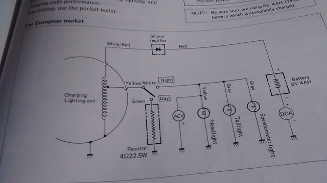
4 ohms - 22.5 W
Mine mounts to the battery box, near the half wave rectifier and is wire wound. When looking for this in the manual I noticed that cct. diagrams for USA models sometimes showed an actual regulator in the circuit.
Cheers Geoff
4 ohms - 22.5 W
Mine mounts to the battery box, near the half wave rectifier and is wire wound. When looking for this in the manual I noticed that cct. diagrams for USA models sometimes showed an actual regulator in the circuit.
Cheers Geoff