Page 1 of 3

W/pump cartridge removal idea.

Posted: Fri Oct 02, 2009 9:55 am
by Suzsmokeyallan
I was looking at the upper cases of a spare buffalo engine I used to fit the GS 750 gearbox into and thought, "what if" (and for me thats dangerous territory), I could make the water pump cartridge easier to remove.
Now i see a simple alteration can be done to accomplish this:::
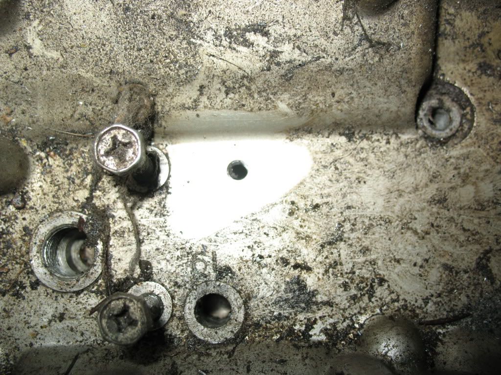
Look at the top inner cases of a Buffalo engine and you will see the top of the pump shaft sits in a bushing, nothing special there, BUT in the centre of this bushing casting it faces the flat portion well of the starter motor on the other side.
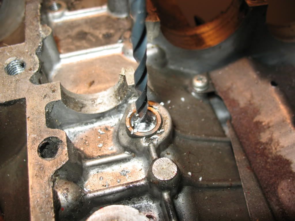
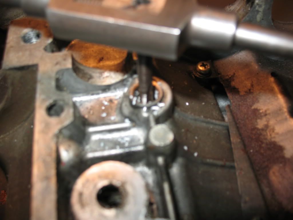
So why not drill a 6mm hole into the centre of the bushing well and tap it, then you can put in a short 6mm bolt with a copper sealing washer from the starter side.
Now when you want to remove the cartridge, take off the lower parts as normal and the large snap ring, THEN remove the carbs and starter bits, unscrew the bolt you put in and tap the head of the pump shaft down with a flat faced drift.
It may seem like a lot of work to some removing carbs and the starter motor parts etc but if you've ever had to pull an engine apart to get the cartridge out, suddenly this idea seems so much easier and cheaper too.

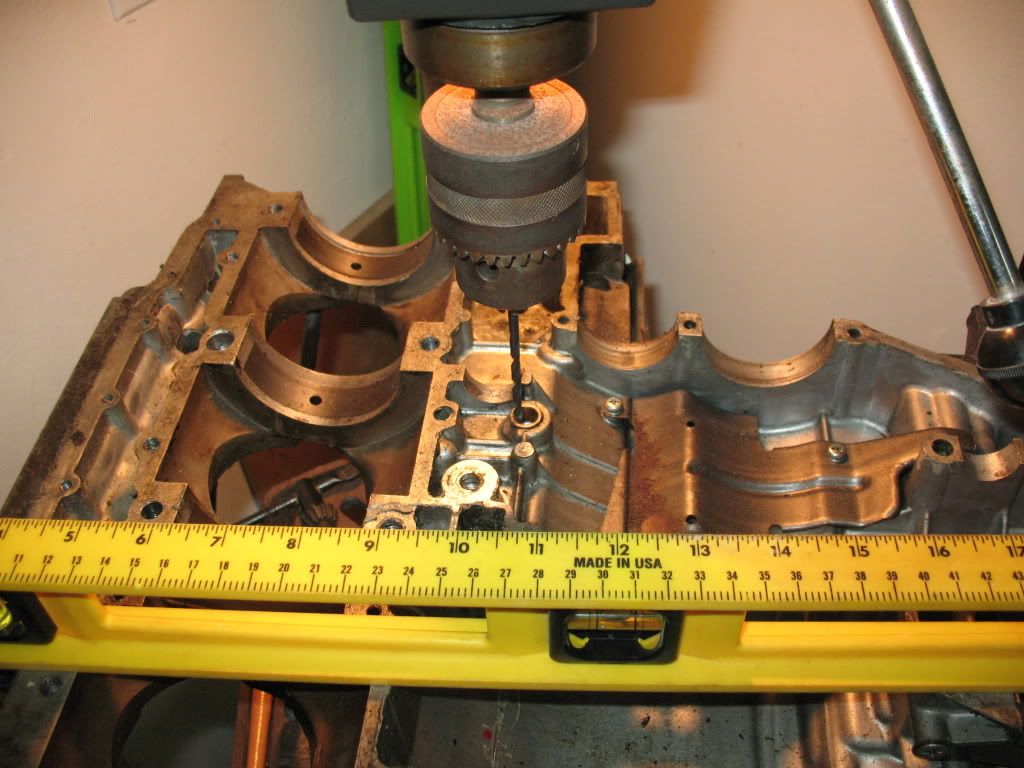
*Update* I have mapped the location of the hole for the exact point to drill from above by doing a spare case beforehand and have supplied those reference measurements for where the hole should be in a post on page two*.
This way if you are wanting to remove your pump for service you could use the measurements and drill the hole from above and tap the cartridge out without taking the engine apart if its being difficult to remove from below.
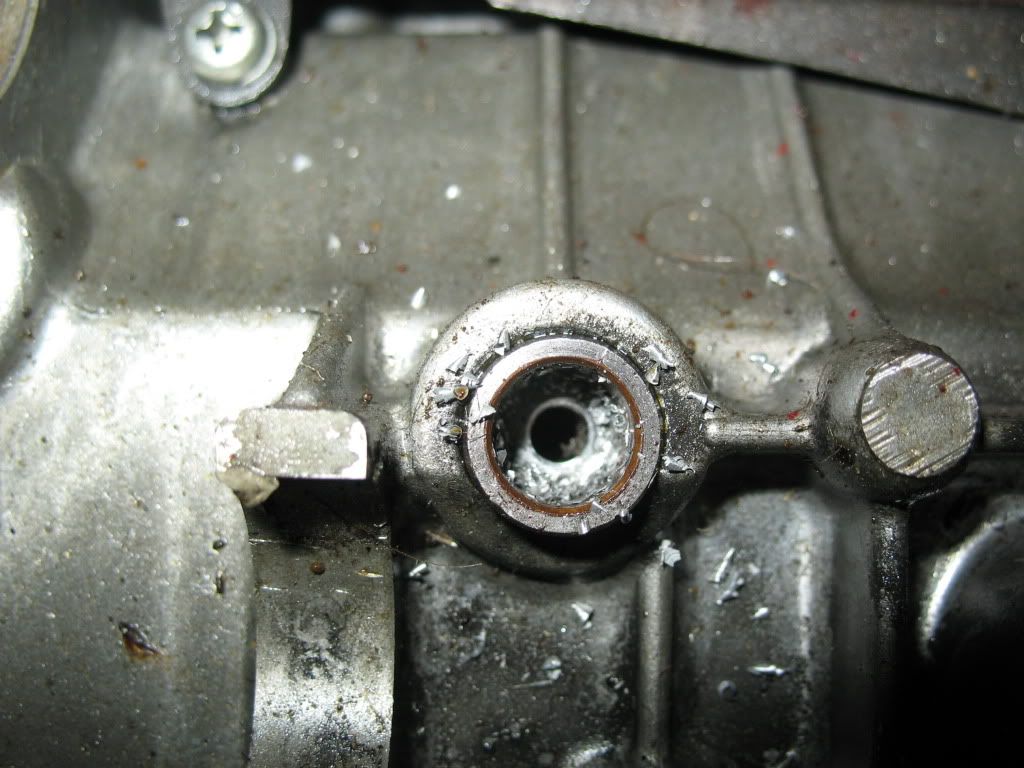
Naturally you would thread the hole after and clean up all the shavings once the cartridge was out.
Generally speaking this idea would be a bonus on any engine since its easier to be able to just tap it down from above than to be under the engine trying to shift the cartridge down with all sorts of creative ideas.
I'd like to hear the opinions of those interested in this.

Posted: Fri Oct 02, 2009 3:30 pm
by oldjapanesebikes
Just double checked against the engine I'm doing right now, and I agree it could work - if I have a hesitation it is that the casting is quite thin so there isn't much there to thread, but that's a side issue. It could be a handy trick to have up one's sleeve.

To be honest, my own experience has been that so far I haven't had to do anything to the water pump by itself, and have only ever serviced them when I had an engine out for something else. Of course having said that, I've now put the curse on myself and can expect to find all my Buff's with a puddle under them tomorrow morning :D :shock: :D :shock:

Posted: Fri Oct 02, 2009 3:33 pm
by Suzsmokeyallan
Ian surely you jest, WHERE on a buffalo engine is the casting ever thin.
If you're putting your mouth on your bikes you better walk into your garage tomorrow with your eyes closed OR you can follow the green trail if you wish.

Posted: Fri Oct 02, 2009 3:57 pm
by oldjapanesebikes
Well - its all relative of course :D

There look to be a few spots where its measures about 3 mm, which isn't what I'd call thick - given its a soft alloy I personally prefer to have a bit more meat if I'm going to want to thread something. No idea at all how thick it is at the point where it would need to be drilled, but there is an easy way to find out ! :D

Posted: Fri Oct 02, 2009 4:37 pm
by Suzsmokeyallan
Yup there is Ian and i plan to drill that same case to see just whats the deal there. Its not like it needs to be super thick anyway because you could put in a bolt with some blue loctite and snug it up and it would stay firm.
3mm thickness would be more than enough for it to hold and work.

Posted: Fri Oct 02, 2009 6:30 pm
by Suzukidave
I like that idea so much i am going to put it in the project bike engine :D

Posted: Fri Oct 02, 2009 8:36 pm
by Suzsmokeyallan
There you go Dave, i plan to get around to the 73 cases this weekend and see just what it all works out to be.

Posted: Sat Oct 03, 2009 3:31 pm
by Suzsmokeyallan
And here we are on the project, I centre punched the hole from the inside first, next the oily/dirty donor case was inverted and levelled to the inner case halves on the drill press table.
Then I started with an undersized drill and worked up to the size for finally tapping it at 6Mx1.00.
Once I was drilling the hole I knew it was thick by how much material was coming out.
The good news is the depth of the case material here works out at approx 6mm, more than enough for a bolt and copper washer.
The upside photo shows its far enough away from the angled portion of the casting by the clutch bulge, again a wonderful bonus.
I'm going to map the holes location by some reference points on the top case so it can be done from above on an engine already in the frame.
Since the two starter bolts are close to the hole it would make sense to use those holes as a guide and triangulate the three for a simple template.

Image
Getting it perfectly level on both planes


Image
Drilling the hole out


Image
Tapping it at 6Mx1.00


Image
Finished look from underneath


Image
The look from above and the case is 6mm thick. The two philips head bolts shown are the starter bolts.

Posted: Sat Oct 03, 2009 5:05 pm
by Suzukidave
Good Deal Allan , looks like it worked out just as planned :D

Posted: Sat Oct 03, 2009 6:09 pm
by oldjapanesebikes
very nice indeed Allan - and also good to see its off to the side a bit so there should be zero chance of interference with the underside of the starter motor and the head of the 6 mm bolt as well. I'd guess in that location there should be perhaps 5 mm clearance to play with ?

Posted: Sat Oct 03, 2009 7:23 pm
by Suzsmokeyallan
Ian if you remember the starter is on legs where it bolts into the two 6mm bolts shown in the pic so its not that close to the housing. Also that main engine case bolt at the bottom of the pic just opposite the new hole is more in the way yet it clears the motor housing, so all will be ok.

Posted: Sat Oct 03, 2009 10:58 pm
by oldjapanesebikes
Yep - I remember it well Allan - which of course is why I'm happy it looks as good as it does.

Posted: Sun Oct 04, 2009 12:37 am
by MotoMartin
Hi Allan,
Do you have the triangulated measurements (or template drawing) that I can use to try this?
Thanks

Posted: Sun Oct 04, 2009 4:36 am
by Suzukidave
I do wonder how much drilled / tapped material would get into the transmission if you tried this on a still assembled engine ?

Posted: Sun Oct 04, 2009 7:00 am
by Suzsmokeyallan
Dave if the engine was upright practically none should stray as they should stick to the top portion of the oily pump shaft/cartridge.
To make sure this happens you could inject some grease into the hole before tapping to help the swarf stay in a blob.
Once you tap on the shaft and it drops down most if not all should stay on the pump shaft and top area of the cartridge due to there being oil residue or the grease you put on it.
I guess you could also try vacuuming out the hole of the excess material before you tap the shaft down to see how much you can remove beforehand.
Even if one or two pieces go into the engine, its soft aluminum anyways so an oil change should get rid of it.
Considering what ive seen that usually comes out at an oil change, a few pieces of aluminum seems immaterial in comparison.
Of course once the pump is out you can then see how much was left in the upper boss area by visually checking it.

Martin I'll have to get my butt in gear and make the template hopefully today so ill be posting it as soon as i can make it up.
I have to use the template setup on my bike in Canada as well, so next summer ill be drilling and tapping that one for pump removal and refurbishment.
Since i have no history of just whats been done in there prior to me buying it im not even going to try and remove it without doing the top hole update.