Page 1 of 1
T500 electrical...
Posted: Tue Nov 25, 2014 4:06 am
by Fritz500
I replaced my voltage regulator in my 73 T500 about six months ago and all has been sweet until today.
The indicators work fine with the engine off but flash like crazy when the engine is running. Battery voltage measures about 14.5v with the engine at 2000 rpm. With the engine stopped it measures about 12.6 volt.
I assume the regulator is on the way out...
Any thoughts gentleman?
Cheers
Re: T500 electrical...
Posted: Tue Nov 25, 2014 5:49 am
by ConnerVT
Could be. I would check connections first. Be sure that it has good ground connection, and all other connectors are clean and solid.
The regulator kind of "hangs on" the charging system (more precise, it is wired "in parallel"). It passes (shunts) excess current when the voltage gets over limit, reducing the voltage for the system.
Re: T500 electrical...
Posted: Tue Nov 25, 2014 7:59 am
by jabcb
14.5v @ 2k rpm is fine.
The stock voltage regulator doesn't regulate voltage like modern regulator/rectifiers do -- it just prevents the voltage from getting too high.
Your regulator is OK along as the voltage doesn't get above 16v at high rpm.
Your flasher may be on its way out.
Alternatively if you just replaced turn signal bulbs you may have replaced them with bulbs that are too high wattage.
Re: T500 electrical...
Posted: Tue Nov 25, 2014 2:55 pm
by Fritz500
Thanks for the tips guys.
I'm going to swap over with spare units one at a time. The flasher is the original unit and the flasher bulbs them selves were installed about 3 years ago and are all the right sorts. I'll check all the connections while I'm at it.
I know why she's doing this to me...I have two other projects on the boil and she's jealous!
Cheers
Re: T500 electrical...
Posted: Sun Nov 30, 2014 3:24 am
by Fritz500
I found a spare voltage regulator and swapped it over. All the connections to the old one were good. Nothing loose and the plugs were all a very tight fit (hard to unplug!).
Popped the replacement one in and the indicators worked perfectly. Neutral light stayed a constant brightness whereas it varied a fair bit with the old unit.
Checked the resistance of the old unit:
- Orange to red/green - no continuity
- Red/green to black/white - - no continuity
- Orange to black/white - 1140 ohms (supposed to be around 1000 but close enough)
So I don't know what going on.
I may buy a spare voltage regulator just in case.
Cheers
Re: T500 electrical...
Posted: Fri Dec 05, 2014 8:56 am
by Fritz500
Can anyone help me design a voltage regulator
I assume the circuit is a simple as this:
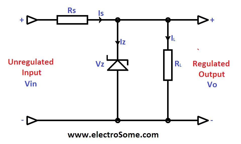
I wasn't sure what ratings etc I'd need for each component.
I want to try one for the T500.
Cheers
Re: T500 electrical...
Posted: Fri Dec 05, 2014 3:33 pm
by jabcb
A better & easier solution would be to upgrade to a modern rectifier/regulator like the Tympanium.
You'll get much better voltage control than with a simple zener diode voltage regulator.
For more info see:
viewtopic.php?f=2&t=4858&p=109480&hilit ... um#p109480
Re: T500 electrical...
Posted: Fri Dec 05, 2014 11:21 pm
by Fritz500
jabcb,
Thanks for the reply.
Yeah I'd looked at them before when I was having issues. I wanted to make my own and hollow out my old non-working one and stick it inside. I have time on my hands and enjoy stuffing around.
My other hobby is model subs. Here is a photo of the 3 control boards I did. I needed a circuit that would allow one channel of the RC gear to control 3 things (operate air release to ballast tank, operate water pump or start air compressor).
The first one (on the left) I rewound a could of 12 volt relays so the coils were 6 volt. Then I thought I'd use transistors. Too much voltage loss. Went back to smaller relays and used smaller transistors to do the switching. My mates mocked me and said use an Arduino or upgrade my RC gear. I like to do things my way...stubborn all the way.
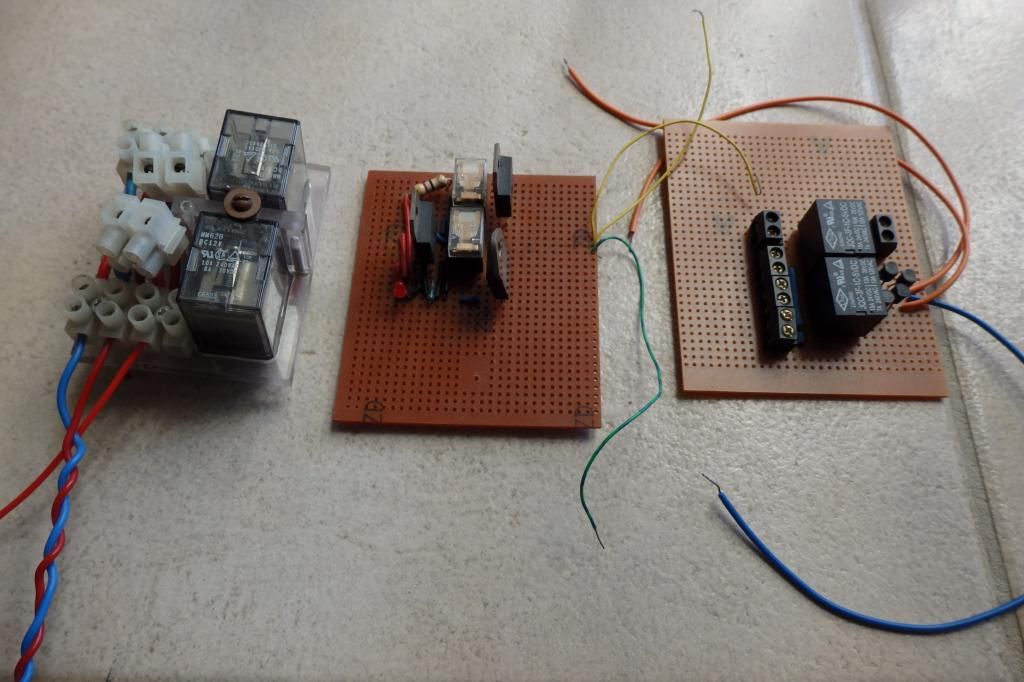
With me it is the journey...
Cheers
Re: T500 electrical...
Posted: Sat Dec 06, 2014 7:33 am
by ConnerVT
It's certainly OK to make your own. The T500 electrical system is pretty basic (wouldn't want to do it for an electromagnet alternator).
A couple things to keep in mind --
The stock regulator hangs on the input side of the rectifier (across the alternator output) and not on the DC output side (across the battery). So it is regulating AC, not DC. Also, be sure to size components to handle the amount of current it may potentially see.

Re: T500 electrical...
Posted: Sat Dec 06, 2014 10:09 pm
by Fritz500
ConnerVT,
Don't make it sound too complicated as my old brain will explode!

I'll keep looking for a circuit diagram on the Interwebs...
Cheers
Geoff
Re: T500 electrical...
Posted: Sun Dec 07, 2014 7:00 am
by ConnerVT
Sorry. No pain intended.
Typically voltage regulators are connected on the output side (DC) of the rectifier. This will be the vast majority of circuits you will find on the Internet. The T500 has an AC voltage regulator, which is on the input side of the rectifier.
The AC regulator is a bit more complex, but has the benefit of generating a bit less heat, so smaller components/heatsink is required.
Re: T500 electrical...
Posted: Sun Dec 07, 2014 7:33 am
by Fritz500
ConnerVT
Ta!
I don't suppose you can point a few suitable circuits out to me?
Cheers


