Page 1 of 2
GT500 CDI
Posted: Mon May 03, 2010 12:59 pm
by rbond
OK folks, here is the home brewed CDI for a GT500. Thanks to Phil C in England for his electronic expertise[IMG]
http://file.walagata.com/w/sundialmotos ... I.jpeg[IMG]
Somehow I did not do the image thing right. But copy and paste the url for the image and it will display.
Picture Linked
Posted: Mon May 03, 2010 1:43 pm
by krwalsh

You need to press the IMG button after the link as well, to "close" the link.
h,mmm
Posted: Mon May 03, 2010 5:22 pm
by gyrocfi
Okey Dokey then!! Thanks lots for the info. That's gonna be a great way to replace the iggy. Dofin
Posted: Tue May 04, 2010 1:01 pm
by diamondj
So I'll admit my ignorance of all things electrical now and start asking questions....
1. This replaces the little silver box of magic smoke in a GT500 PEI ignition right?
2. The boxed values indicate components used in the circuit? Where would you recommend buying these? Is there a good on-line retailer?
3. Any chance you can post a short tutorial on how to put one of these together? Looking at the diagram, I'm not entirely sure how it all works....
Thanks,
Jim
Posted: Tue May 04, 2010 6:28 pm
by CJF
+1
Posted: Tue May 04, 2010 11:00 pm
by oldjapanesebikes
diamondj wrote:So I'll admit my ignorance of all things electrical now and start asking questions....
1. This replaces the little silver box of magic smoke in a GT500 PEI ignition right?
First of all, I think Robert has done a great job with this - I take my hat off to him ! It may folks help to take a look at Robert's diagram along side this one - the colour codes for the wires match and show how the ignition circuit fits together.

diamondj wrote:2. The boxed values indicate components used in the circuit?
Correct - that is the parts list of components required to make the CDI unit
diamondj wrote:Where would you recommend buying these? Is there a good on-line retailer?
Most of these are fairly common components - Radio Shack in the US carries most it not all of it.
diamondj wrote:3. Any chance you can post a short tutorial on how to put one of these together? Looking at the diagram, I'm not entirely sure how it all works....
There was one photo in one of his previous posts showing the mock-up, so perhaps just a photo of the 'production' version would be enough - that part I'll leave to Robert

but I do think this thread should be made a sticky.
CDI
Posted: Wed May 05, 2010 3:42 pm
by rbond
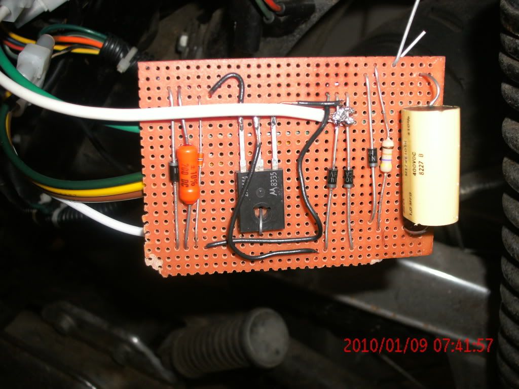
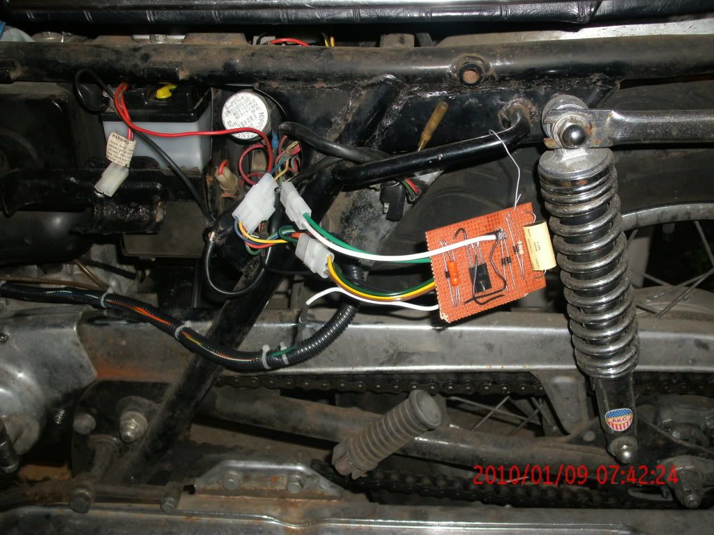
Best place on-line to get parts is 'digikey.com'. The prices are good and fast delivery. For each part you search for will be a long list from many vendors. It may help if you have a 'electronics' knowledgeable friend to sort it out. First best place is any local electronics parts house, excluding Radio Shack. They simply do not have all the parts. The more parts you can get at one place the better. The pictures I showed earlier of the circuit hanging off the side of the bike was an actually working unit. It was done that way just to test it out. This will also give you an idea as to where the parts roughly go on the board. Since it produces no heat, you may sandwich it in some foam rubber for vibration control in a (you ready?) black box.

I put mine where the tool kit would go, only because I don't have a tool kit. If your OEM CDI is for sure blown, cut off the wires close to the box and use those to connect your homebuilt unit with. The very first item to check is the coils on the stator, I have had these go out on me twice, the CDI was still good. The highest price for everything was about $60.00. I have it down to about $25.00. An OEM CDI is about $216.00. At these prices, build two, mount both. IF, IF one blows in the middle of nowhere, swap wires and bang! your running again.
The red wires are jumpers, I used the long leads on each part to connect to each other, my soldering stinks, but for this it works good anyway. There are a few generic CDI circuits out there, but are designed to run from a battery.The GT's runs off the magneto. Also, I replaced the ignition coil from Dyna S. It was electrically an equal to the OEM at half the price. (It was for a Harley).
Posted: Wed May 05, 2010 4:24 pm
by diamondj
Thank you for posting this!
Looking at your pictures makes it a bit clearer for me:
Jim
CDI
Posted: Thu May 06, 2010 10:00 am
by rbond
In the pictures diamondj shows is the latest board I made. I did not have any more of the OEM connectors, so I put new ones on and replaced(made) the wiring harness from the stator (zip tied plastic tubing). The old wiring had some very brittle and breaking insulation, replacing was mandatory! The board is approx. 2" x 3", on the flip side is where most of the soldering/connections are. Nothing fancy, just loop the leads from each part together and solder the stuff. It does not look pretty, but keeps everything connected. I ran the original circuit for a year and a half when I started having problems. It finally turned out to be two bad coils on the stator, but I had by then wrecked the first circuit trying to find out what part failed. I had coated it with liquid vinyl in an attempt at vibration / moisture control. I had to use a dremel to clear some of that hardened goop out. So I changed that to foam rubber and a thin bead of gasket sealer around the edges of the black box. Makes it much easier to replace innards if needed in the future.
part update
Posted: Mon Jun 21, 2010 2:39 pm
by rbond
The thermistor 'AL3006-1847-76K' needs to changed to 'AL3006-1847-76-G1'. As of 6-21-2010 it costs $3.25 at Digikey.com. It is a hard to find part and that is a very good price.
Re: part update
Posted: Mon Jun 21, 2010 4:10 pm
by diamondj
rbond wrote:The thermistor 'AL3006-1847-76K' needs to changed to 'AL3006-1847-76-G1'. As of 6-21-2010 it costs $3.25 at Digikey.com. It is a hard to find part and that is a very good price.
Okay, I tried to look up some of the parts on the list above at Digikey and got lost really quickly. On the revised part above, should there be an extra zero between the AL and 3006? Because I can find it that way. For the diodes, I entered "diode 1N4007" and I get a set of filters that include manufacturer, forward voltage, reverse current leakage, capacitance, etc... The one combination that seems to work yields this part number:
1N4007-TPMSCT-ND
Is this the right diode?
I'm assuming C1 is a capacitor? I *think* this one has the right specs but I'm not sure:
P4717-ND
R2 seems like a pretty standard resistor although the only one I can find on digikey that matches the spec has a minimum buy of 1,000 with an extended price of $43. This used to be something Radio Shack sold so I could always check there unless you can recommend a part number from digikey?
C2 - searching this one I find 495-2986-ND which is a film capacitor and seems to have a much longer lifespan than the aluminum ones. Is this the correct part number?
SCR - the rectifier. The Philips number yields:
568-3674-5-ND
The Motorola 2N4444 doesn't return a match and I don't seem to get a match on ECG/NTE 5448 either.
So to sum up your parts list with what I've found, I have:
D1 - 1N4007-TPMSCT-ND
C1 - P4717-ND
R1 - AL03006-1847-76-G1
D2 - 1N4007-TPMSCT-ND
D3 - 1N4007-TPMSCT-ND
D4 - 1N4007-TPMSCT-ND
R2 - no cost effective match found at Digikey
C2 - 495-2986-ND
SCR - 568-3674-5-ND
Am I right on any of these???
Thanks!!!
Jim
CDI
Posted: Tue Jun 22, 2010 9:57 am
by rbond
Here you go diamondj,
1N4007GOS-ND (1n4007) diode $0.34ea.
KC006G-ND (AL3006-1847-76-G) thermistor $3.25
CMF47.5KHFCT-ND (47.5ohm) resistor $0.16
EF4105-ND (1.0uF 400V) capacitor $1.00
568-3674-5-ND (BT151-650) scr $0.82
EF1223-ND (.022uF 100V) capacitor $0.36
On the .o22uF, it is the same as a 22nF.
So, not including shipping, everything here runs to $6.95!!

I positioned the parts so the leads from each part would reach the ones needed to be connected to one another. In that, I wrapped the leads together, soldered them, and then soldered the external wires to the leads wherever was handy. The external wires may be soldered top side or bottom side, don't matter, as long as it is the correct lead. If you have ever worked with these parts before, the positions of the diodes and the scr connections are the only 'critical' ones to pay attention to. As you see in the pictures, parts placement is identical to the schematic. Phil did this on purpose to make construction a breeze. I have assembled a few electronic kits in my time, this is the easiest one yet. Any questions, hit me up!!!
Voltage regulator
Posted: Tue Jun 22, 2010 12:27 pm
by rbond
I have replaced my V/R with a unit from Electrex in England. About $35.00 USD, it seems to work pretty good, but does overcharge some. I use my bike as a daily driver so I get to put an average of 120 miles a week. Anyway I have to add water at least once a month, not too much, the plates are still covered, but the level is noticeably down. In the same vein as the CDI, I went internet trolling and found a circuit for a GT500!! I have built one, but have yet to test it. I will keep anyone interested, posted on the V/R. If you look at the factory color schematic, you can see the V/R has next to nothing for parts, so price should be very cheap. I do not remember how much I paid for the one I built, Alzheimers' I guess.......
Posted: Wed Jun 23, 2010 2:40 pm
by oldjapanesebikes
Looking forward to hearing how the V/R testing goes !!
Re: GT500 CDI
Posted: Sun Nov 14, 2010 4:25 pm
by Suzsmokeyallan
I'd say on a Titan a slight overcharging VR would be better since the stock one is pitiful and the bike does not like a weak battery. The downside is frequent lower water level but again thats less of an issue if you maintain your bike often and check the water level.