Clean coil with new HT lead closeup view.

After the HT leads were replaced, some protective sleeves now need to be added to prevent shafing again the frame rails under the tank just as the originals had.
Moderators: oldjapanesebikes, H2RICK, diamondj, Suzsmokeyallan
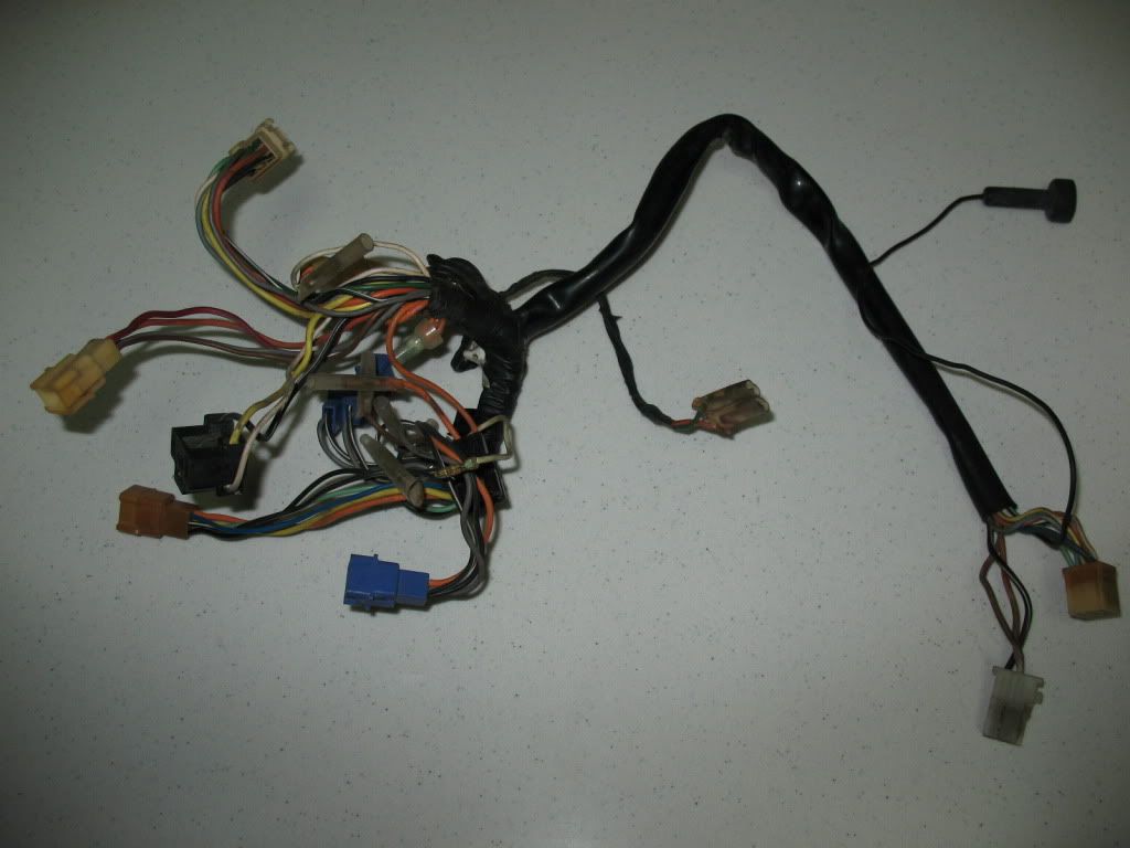
Suzsmokeyallan wrote:Here I have a front main harness assembly for a Buffalo, its the usual looking suspect bought off of Ebay as part of a whole harness and its related parts.
This one is a late version type as it has the round pin type of socket by the ign coils connections.
I'm also going to modify this for a few improvements over the stock harness that will make it better than how it was.
The list of things done will be along these lines:
Strip all the tape and sheathing off.
Remove all the sockets and clean them and the connectors, suspect ones will be replaced.
Test the wires for continuity and repair any issues.
Retape it and fit new sheathing.
The upgrades will be:
Change some of the sockets to a different style for a better interface.
Change some of the wires to a different gauge for improved current flow.
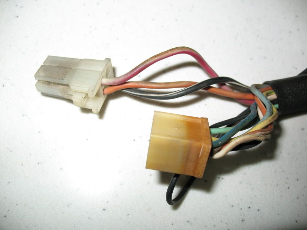
The harness as it was bought, 30 plus years old
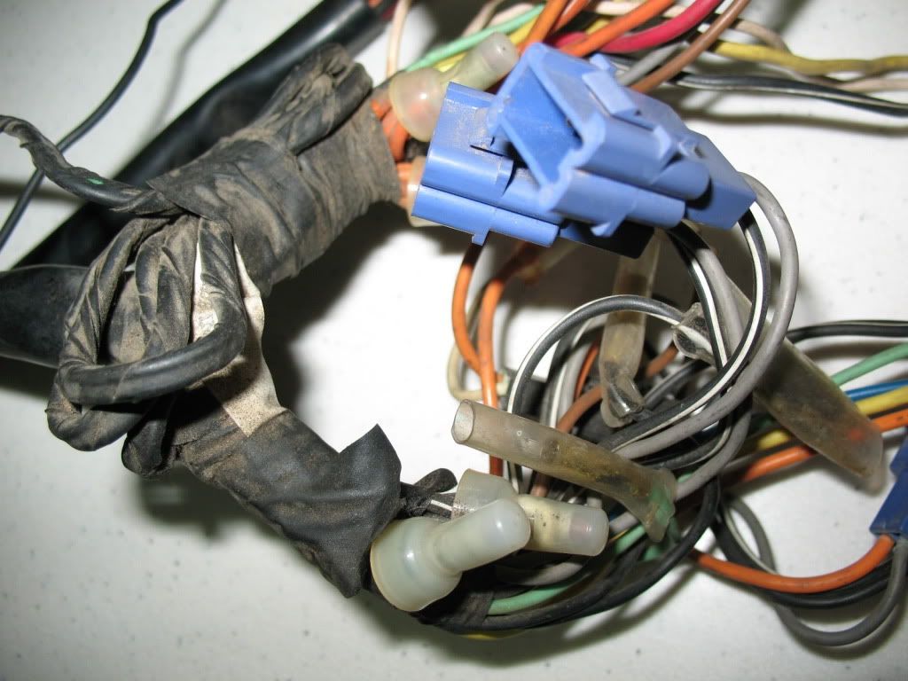
The tapes coming off and its got some visual problems, dirty connectors, corrosion in the terminals, and of course a melted one.
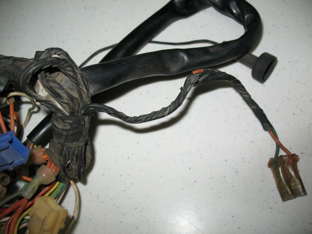
The worlds longest Buffalo horn wires as fitted from the factory and then taped up in a bundle. I have not undone these but they are easily two feet long. How about a horn on the front fender tip for a change as this could reach there easily. What were they thinking?
This socket was the one from the gear indicator harness that I temporarily swapped out as I needed one that had good clips.
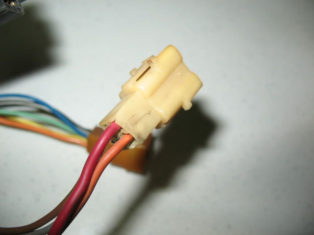
The main harness connectors, the white one above is the main power wires from the rear harness and battery. You can see the red and orange coloured ones are faded, which means this bike was somewhere out in the open with the tank off for quite a while.
This is a very weak point on these harnesses and usually these are burnt up or showing signs of melting, it definitely needs an upgrade.
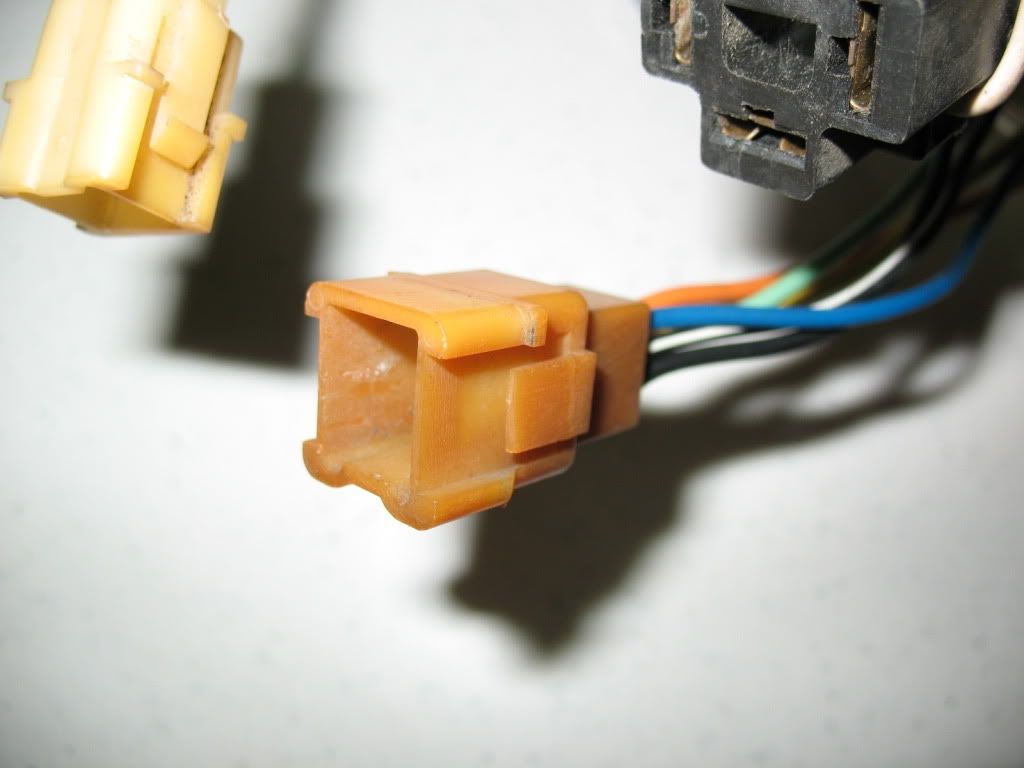
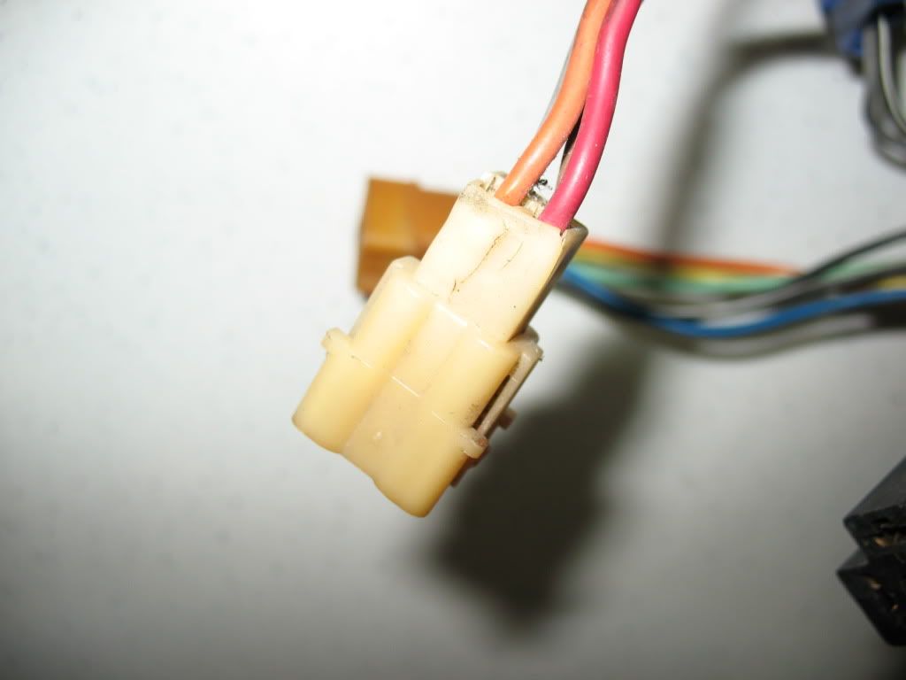
The ignition wire socket to the switch, as usual its melted and will be upgraded, this is also a common problem.
Another view of the same melted socket, this is very dangerous as it sits inside the H.L bucket, which means there's grounded metal all around it.
Just so you know, I've got some other work to do for restoration purposes so I'll get to this when I have some spare time and keep you updated accordingly.

Use a decent multimeter on 'Ohms' - Ω - and put the leads together to see what resistance is in the leads. Remember that number, it should be very low, like 0.1Ω (ish) if you have decent quality test leads.TJCOOL wrote: have to ask because i don't know..how to you test the wires?
Alan H wrote:Use a decent multimeter on 'Ohms' - Ω - and put the leads together to see what resistance is in the leads. Remember that number, it should be very low, like 0.1Ω (ish) if you have decent quality test leads.TJCOOL wrote: have to ask because i don't know..how to you test the wires?
Now test the wire you want to know the condition of WITH NO POWER ON IT.
If it has power on it, you could blow the tester fuse or even bugger it up completely if it's a cheap one.
Now subtract the test lead number from the wire number and that is the resistance of the wire.
This should also be very low - if it gets over 0.5Ω, there's a bad connection somewhere, the wire is very thin, or the wire is partly degraded/broken.
Note that on short runs of wire, the resistance will be almost the same for thick and thin wires, but if you intend carrying heavier currents (spotlights or air horns for instance) you need thicker wires and better connectors to carry the current.
In case you are wondering, I'm a recently retired Electrical Engineer, but only been in that trade for about 49 years, so still learning!!
Sounds like you may have an inexpensiveTJCOOL wrote:my meter has two settings for Ω's..X1K and X10....which one of these will give me the readings I need to take? When I do the leads test..touch them together?..i don't know!...they go off the chart for the Ω's readings..for both settings..maybe i have a cheap meter..
Alan H wrote:Sounds like you may have an inexpensiveTJCOOL wrote:my meter has two settings for Ω's..X1K and X10....which one of these will give me the readings I need to take? When I do the leads test..touch them together?..i don't know!...they go off the chart for the Ω's readings..for both settings..maybe i have a cheap meter..meter - mine is a good Fluke meter that autoranges so it sorts itself out.
Use the X1 for wiring and X10 for coils etc.
The reading you have when nothing is connected is usually 'INF' or ∞ (like an 8 on it's side). You can take one wire out of the meter terminal and touch the free end of the test lead still connected, to the empty tester terminal then and see if there is a bad lead - you are only testing one lead at a time then.
It's always good practice to check the leads for continuity every time you use a tester, just in case a lead decides to give up the ghost, or the fkup fairy works her magic while you aren't looking!
If the leads don't pan out good, you may have blown the fuse by using the meter on ohms and testing a power circuit.
Make sure you use the same size fuse as original to keep the tester working, using a nail or silver foil temporary fuse will end in tears.
The thing is, you don't need an expensive meter for 'home/garage' use, just a good quality one. Some fluke models are expensive, but quality wise they are all OK.TJCOOL wrote: that test returns same off-the-charts readings..maybe i should not be so cheap and buy a good one..fluke models are usual quite dear aren't they?