So, I started working on the gauges.
1972 on the Left, and 1974 on the Right.

The PO's of the bikes were hard on the gauges, particularly the '74's.
He said he couldn't see the speedo & tach so he rammed a screwdriver through the plastic and knocked it out.
Damaging the gauge face.

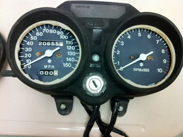
The '72's plastic cover's are so clouded they're unusable.

You can see there's a difference in the wiring on the back of the gauges.

The '74 has the gear selection LED in the center, which I'd like to incorporate into the '72's gauge pod -in place of the "S" symbol.
The '74 came apart rather easily.

I did the same to the '72. I then pulled both gauges out of their housings. (not pictured.)
I removed the needles, and pulled the gauge faces.
I sent them down the hall to the High-Tech lab and had them scanned.
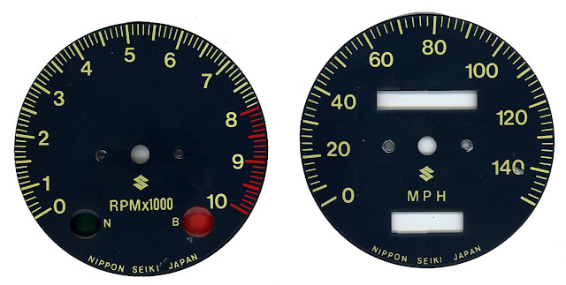
I have them in two formats.
My idea is to change them to white face, black #'s and hash marks, and
RED for the red line.
Then print them out w/ a laser printer, cut them, and stick them to the factory faces. I'm concerned with them fading, but with all the riding I do, I doubt they'll see the sun very much...

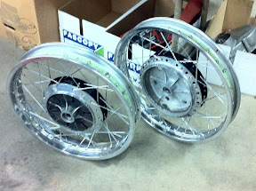
I also started lacing the wheels.
That's interesting....
I had some students start the job and after a couple tries, one student laced the front wheel:
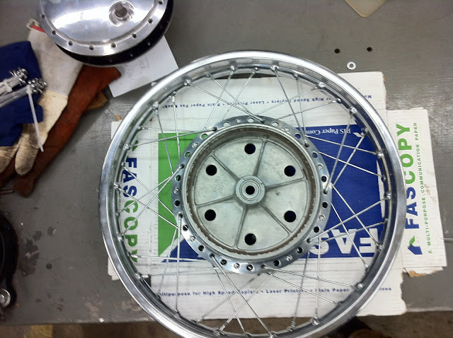

and I took over and finished the rear wheel.
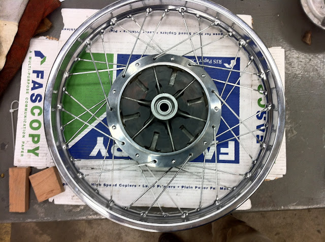
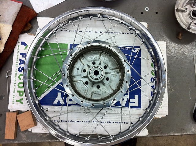
They're just laced and loose. They still need tightened and trued. The real time challenge.