GT550 Cafe project
Moderators: oldjapanesebikes, H2RICK, diamondj, Suzsmokeyallan
-
imquattro
- To the on ramp
- Posts: 239
- Joined: Tue Jul 19, 2011 9:26 pm
- Country: USA
- Suzuki 2-Strokes: 72/74 GT550
- Location: Muncy PA
Re: GT550 Cafe project
Hahaha! Good idea. I've seen people use NOS drink cans (looks just like a shady shot bottle of nitrous).
-
imquattro
- To the on ramp
- Posts: 239
- Joined: Tue Jul 19, 2011 9:26 pm
- Country: USA
- Suzuki 2-Strokes: 72/74 GT550
- Location: Muncy PA
Re: GT550 Cafe project
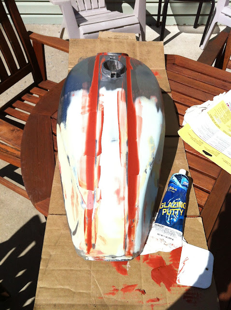
So I finally got the tank back. Big ordeal, bottom line, no charge due to the guy never working on it and having it for 6 months! 
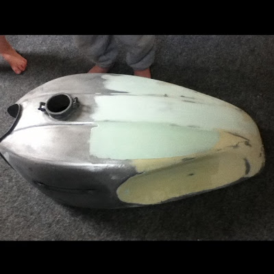
So, it still needs work (progressing this Easter break).
Started working on wire harnessi (plural for harness).
We're finding there were are few changes made between '72 & '74, mostly in the connectors, from bullet style push connectors to modular plugs. There are some extra wires on the '72, like a brown wire from the start/kill switch, that isn't there in the '74's harness (maybe the other way around -I don't remember).
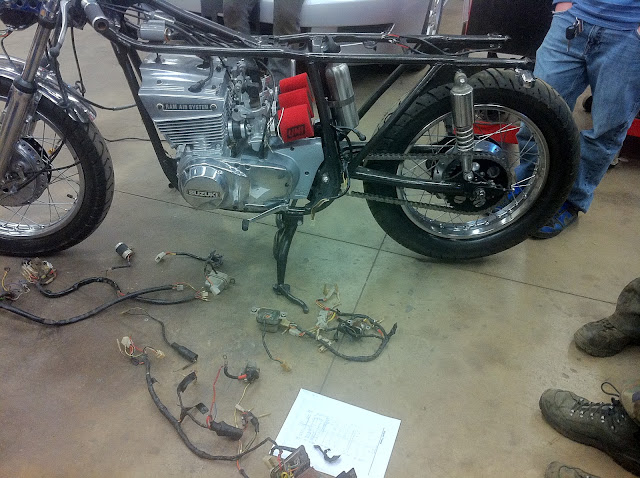
But my students laid out all the wiring from both bikes.
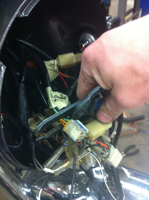
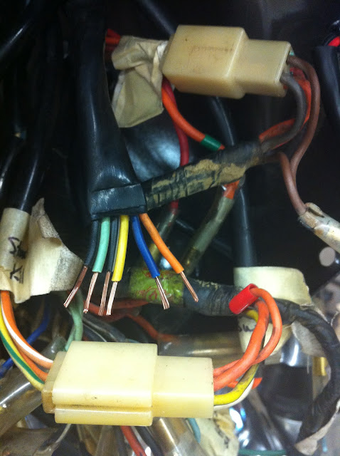
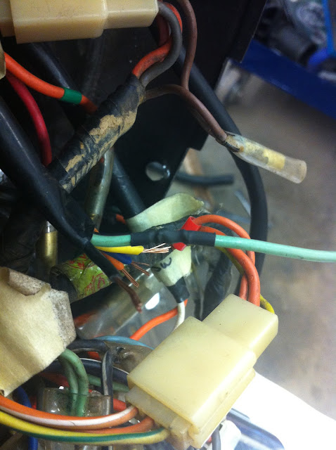
I saw first that the light switch's harness had a different connector than the main harness. 9 pin vs 6 pin w/ 3 bullet connector wires. We took pictures of the orientation on the modular plug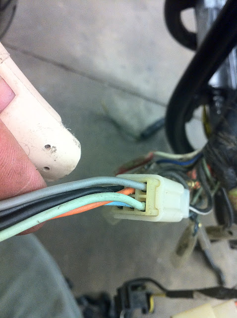 and
and 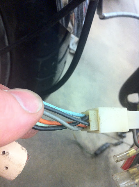 .
.
(Oh, and last week I tore a ligament on my left middle finger... hence the splint)
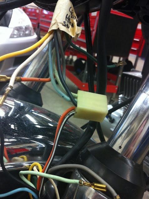
And the culprit: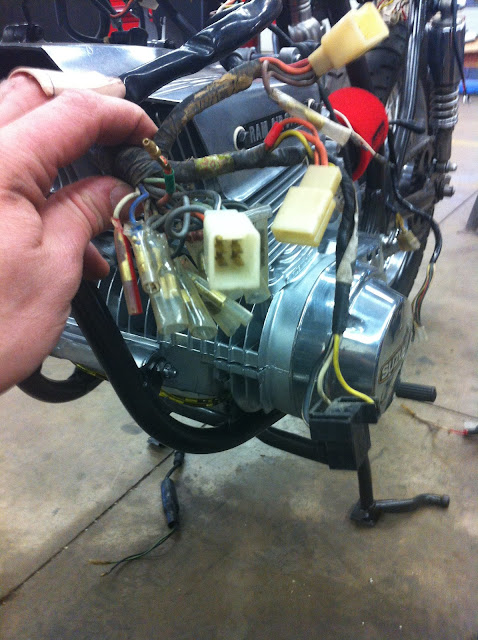
After modifying a paperclip into a connector pin remover (selecting large butterfly clip & filing one end flat instead of a round profile) and removed all the connectors from the 9 pin female connector and then, one at a time, replaced then ones in the 6pin connector on the harness we're not using.
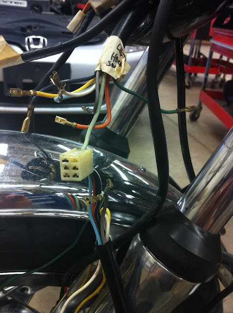
Then we thread through, from the front, the harness from the '74 I believe and connected the now correct & matching plug.
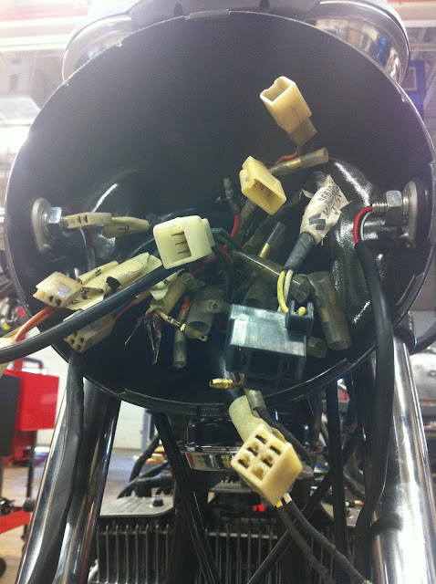
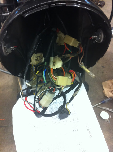
How are the rest going to fit behind the light!?
(see the horn tucked up under the light?)
Next problem: Another connector needed to changed back to the bullet style:
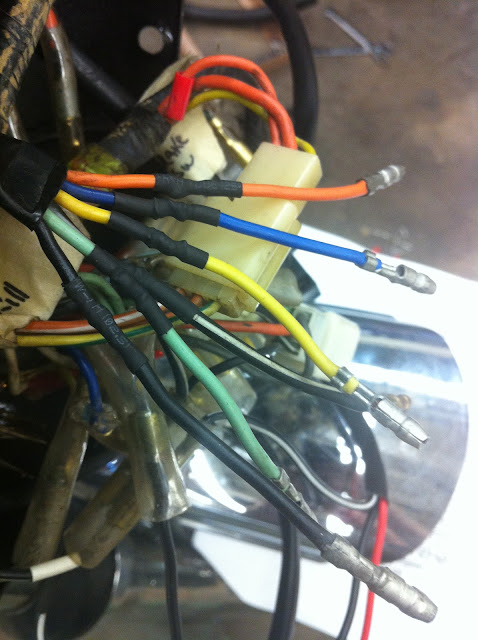
Everything connected:
Next we'll make a shelf for all the electronics to rest and see what parts of the harness need "stretched".
Seems so slow at this point and all I want to do is hear it run!!!
The battery was ordered and should be here next week.
Chose a small battery, may/maynot crank it but should tuck away nicely.
Selected a Ballistic Performance EVO2 50 Lithium Ion 4 Cell
Dimensions (Standard): 2" (L) x 2" (W) x 3.25" (H)
Negative Terminal Location: Right
Weight: 246 grams (.543 lb.)
Voltage (Charged): 13.6V
Amperage: 4Pb-eq/Ah
Pulse Cranking Amps: 80 CCA

Should tuck up under the fuel tank's extended tail section. I'll have to make a foam pocket for it.
So, it still needs work (progressing this Easter break).
Started working on wire harnessi (plural for harness).
We're finding there were are few changes made between '72 & '74, mostly in the connectors, from bullet style push connectors to modular plugs. There are some extra wires on the '72, like a brown wire from the start/kill switch, that isn't there in the '74's harness (maybe the other way around -I don't remember).
But my students laid out all the wiring from both bikes.
I saw first that the light switch's harness had a different connector than the main harness. 9 pin vs 6 pin w/ 3 bullet connector wires. We took pictures of the orientation on the modular plug
and .(Oh, and last week I tore a ligament on my left middle finger... hence the splint)
And the culprit:
After modifying a paperclip into a connector pin remover (selecting large butterfly clip & filing one end flat instead of a round profile) and removed all the connectors from the 9 pin female connector and then, one at a time, replaced then ones in the 6pin connector on the harness we're not using.
Then we thread through, from the front, the harness from the '74 I believe and connected the now correct & matching plug.
How are the rest going to fit behind the light!?
(see the horn tucked up under the light?)
Next problem: Another connector needed to changed back to the bullet style:
Everything connected:
Next we'll make a shelf for all the electronics to rest and see what parts of the harness need "stretched".
Seems so slow at this point and all I want to do is hear it run!!!
The battery was ordered and should be here next week.
Chose a small battery, may/maynot crank it but should tuck away nicely.
Selected a Ballistic Performance EVO2 50 Lithium Ion 4 Cell
Dimensions (Standard): 2" (L) x 2" (W) x 3.25" (H)
Negative Terminal Location: Right
Weight: 246 grams (.543 lb.)
Voltage (Charged): 13.6V
Amperage: 4Pb-eq/Ah
Pulse Cranking Amps: 80 CCA
Should tuck up under the fuel tank's extended tail section. I'll have to make a foam pocket for it.
-
imquattro
- To the on ramp
- Posts: 239
- Joined: Tue Jul 19, 2011 9:26 pm
- Country: USA
- Suzuki 2-Strokes: 72/74 GT550
- Location: Muncy PA
Re: GT550 Cafe project
Where did I leave off???
The tanks coming along... I never have enough time for anything it seems...
In order to smooth out the transition of the tank extension, I've decided to smooth out the hump that runs down the middle. It will still be there, just with less distinction.
Back to the wiring:
Sorting out the wiring between years and components used between bikes for the build has been interesting.
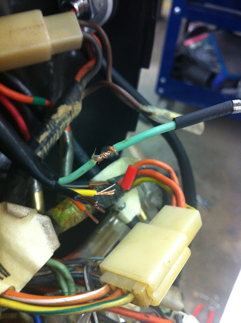
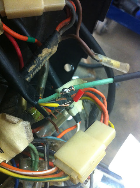
While working through the main harness, we found a main ground had melted throughout some of the harness.

My students removed the damaged portion and replaced it with the good one from the other harness.
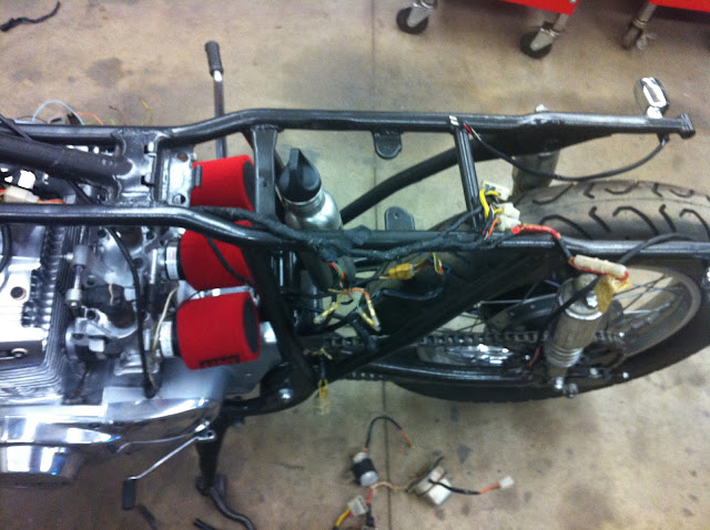
Here my kiddos are lengthening the points wires to meet up with the harness.
Again, we used the wires from the doner bike (so the connections and wire colors all match).
Then there's these:
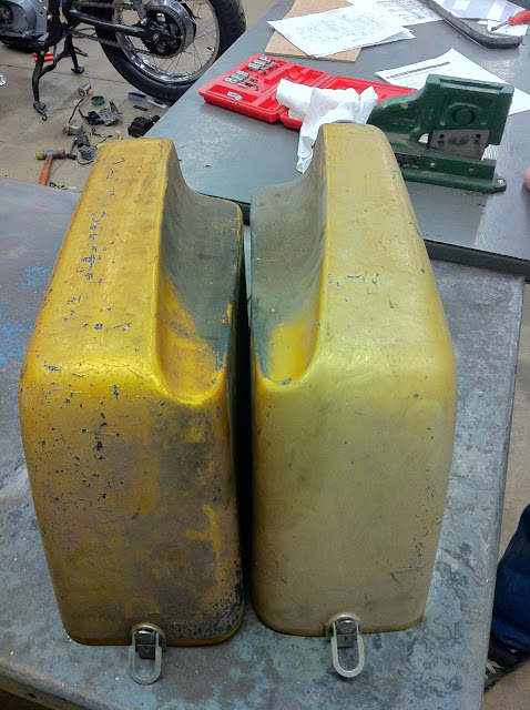
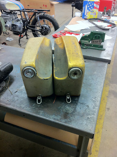
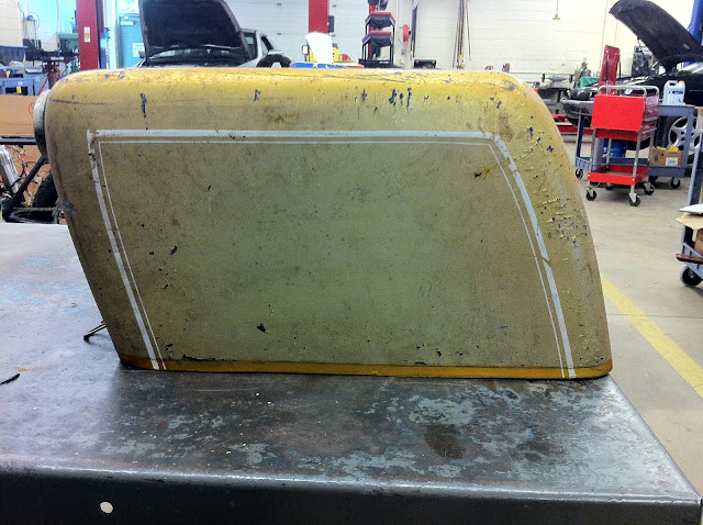
The '72 came with a set of fiberglass hard saddlebags. One was missing a top.
I never had any desire to use them but also couldn't throw them away. I see some use for them....
What can I do with this shape?:
and this tool?
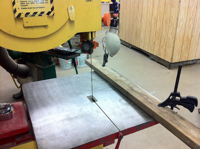
Well, lets cut them down to size:
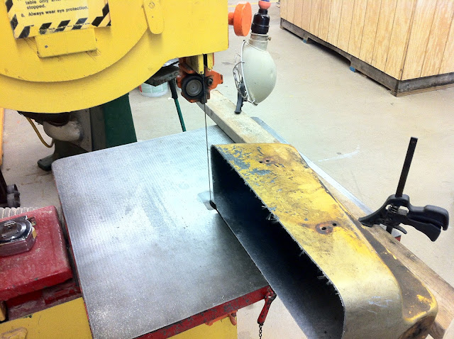
Then trim off the side....
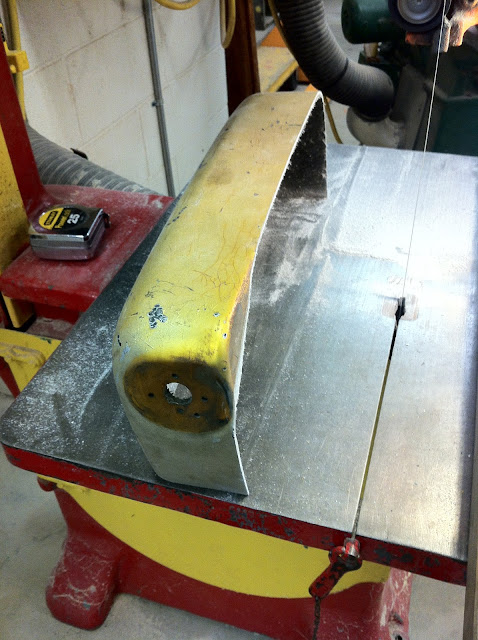
Then stick them together....
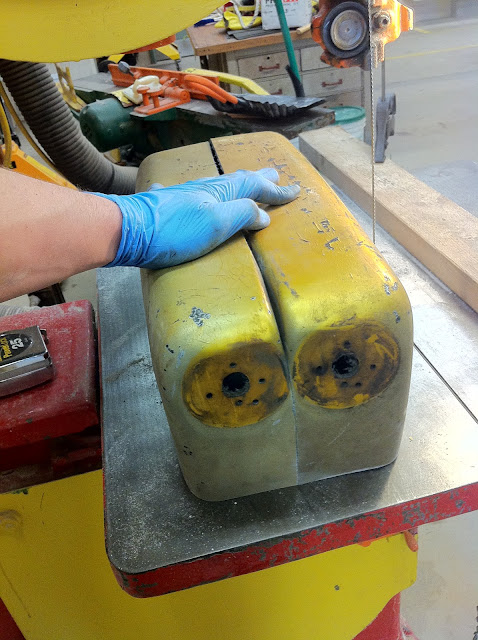
Anyone have any idea where I'm going with this????
The tanks coming along... I never have enough time for anything it seems...
In order to smooth out the transition of the tank extension, I've decided to smooth out the hump that runs down the middle. It will still be there, just with less distinction.
Back to the wiring:
Sorting out the wiring between years and components used between bikes for the build has been interesting.
While working through the main harness, we found a main ground had melted throughout some of the harness.
My students removed the damaged portion and replaced it with the good one from the other harness.
Here my kiddos are lengthening the points wires to meet up with the harness.
Again, we used the wires from the doner bike (so the connections and wire colors all match).
Then there's these:
The '72 came with a set of fiberglass hard saddlebags. One was missing a top.
I never had any desire to use them but also couldn't throw them away. I see some use for them....
What can I do with this shape?:
and this tool?
Well, lets cut them down to size:
Then trim off the side....
Then stick them together....
Anyone have any idea where I'm going with this????
-
jabcb
- Moto GP
- Posts: 4317
- Joined: Mon Dec 13, 2010 4:32 pm
- Country: USA
- Suzuki 2-Strokes: 69 T350 thru 75 GT750
- Location: southwestern Pennsylvania
Re: GT550 Cafe project
You already have the holes drilled for mounting the two combination taillights / stoplights / turnsignals.
BAS (Bike Acquisition Syndrome) - too many bikes but have room for more
Suzuki:
GT750 2x75
GT550 72 & 75
GT380 72
T500 69 project & 73 project
T350 69 & 71
Honda 85 CB650SC & 86 CB700SC
09 Triumph Bonneville SE
Suzuki:
GT750 2x75
GT550 72 & 75
GT380 72
T500 69 project & 73 project
T350 69 & 71
Honda 85 CB650SC & 86 CB700SC
09 Triumph Bonneville SE
-
Coyote

- Moto GP
- Posts: 3404
- Joined: Tue Oct 21, 2008 2:41 pm
- Country: USA
- Suzuki 2-Strokes: GT550x2, GT750, GS1000
- Location: Tulsa, Oklahoma
Re: GT550 Cafe project
Not a clue 
I was born with nothing and still have most of it left.
.
1978 GS1000C
1976 GT550 ongoing money pit.
.
1978 GS1000C
1976 GT550 ongoing money pit.
-
drøn
- On the main road
- Posts: 134
- Joined: Fri Jun 17, 2011 2:36 am
- Location: Copenhagen
- Contact:
Re: GT550 Cafe project
seat bump?
-
imquattro
- To the on ramp
- Posts: 239
- Joined: Tue Jul 19, 2011 9:26 pm
- Country: USA
- Suzuki 2-Strokes: 72/74 GT550
- Location: Muncy PA
Re: GT550 Cafe project
DINGdrøn wrote:seat bump?
-
imquattro
- To the on ramp
- Posts: 239
- Joined: Tue Jul 19, 2011 9:26 pm
- Country: USA
- Suzuki 2-Strokes: 72/74 GT550
- Location: Muncy PA
Re: GT550 Cafe project
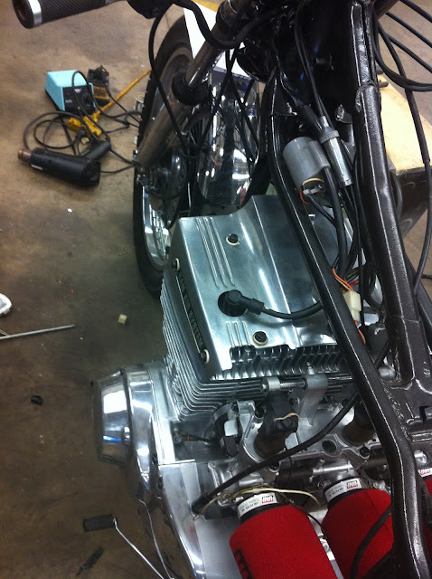
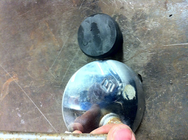
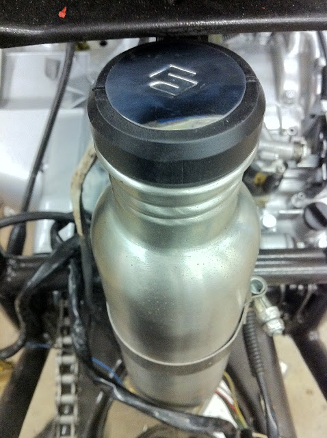
A while back, we created an oil tank from a stainless drink bottle and mounted it on a brace behind the engine:
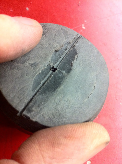
Well, the cap had a loop on the top that 1) interferred w/ any seat pan that'd be made, 2) Didn't breathe or allow air into the tank (and allow oil out respectively) & 3) looked like a drink bottle cap.
So we took the cap over to the belt sander and removed the loop. When doing, so, we found the casting of the plastic was such that there were holes in the portion removed. Yes, it allowed air into the tank, but it also didn't look that great.
So I was thinking.... needs some sort of emblem for the top, 1) to cover the holes visually, and 2.)make it look better:
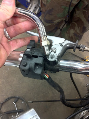
I began looking around through the extra parts I had from the project and saw the "S" Suzuki symbol on the mirror.
I thought, if I could just cut that out, it just might make a perfect fix!
So back to the sander it went:
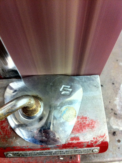
I had measured the desired size circle that would fit on the cap, found the center of the "S" and using that made circle around the "S" to cut to.
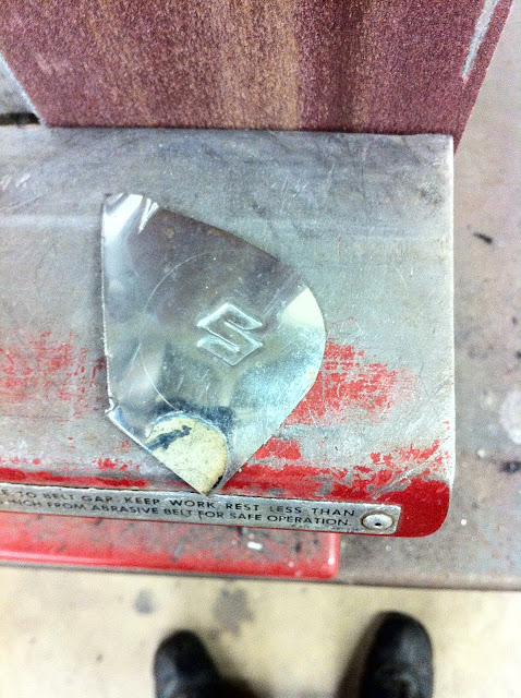
The "S" removed from the mirror assembly:
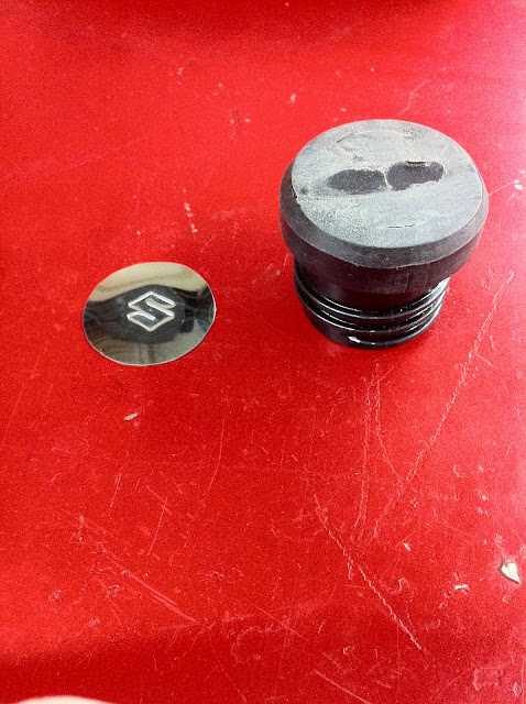
In order to allow air to enter into the container (and allow oil out), a drilled in the center of the cap.

Then a hacksaw blade was used to slot the cap over the hole, so when the emblem was attached, air could travel down the slot, to the hole, under the cap.
Here it is finished:
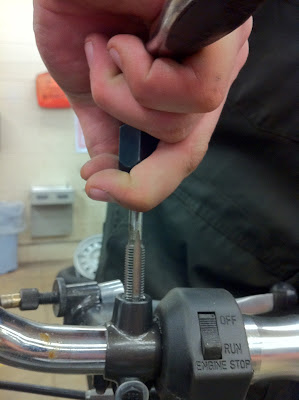
Mirrors were purchased and installed (students had to drill & tap grips out from 8mm x 1.25 to 10mm x 1.25 -practical application of drill/tap chart and application of skills to correctly complete)
Here's a quick couple shots of that starting with a picture taken after one step (of two) drill bits sizes:
Tapping out to 10mm x 1.25:
The shocks that were on the "to get" list were also purchased.
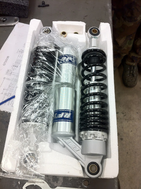
While the original ones are in decent shape, they are corroded and too hard to clean/polish without taking them apart (don't know how they come apart). So they're back in storage:
Last I posted, I was exploring the possibility of making a seat bump/tail from a set of old hard side bags that came with the '72. I had cut them down and even gone to fiber glassing the pieces together but the result didn't flow with the shape of the tank & frame, so it was set aside. I had originally thought I was going to have to mold and glass a seat & bump and was hoping to get around that, but oh well. :O)
I have looked through a LOT of DIY pages on making tails/seats:
For instance: http://www.cafematty.com/making-a-cafe-racer-seat/ and will be doing such.
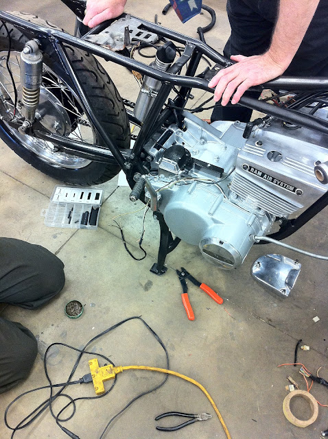
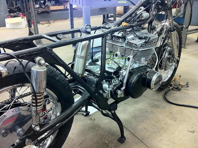
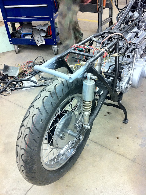
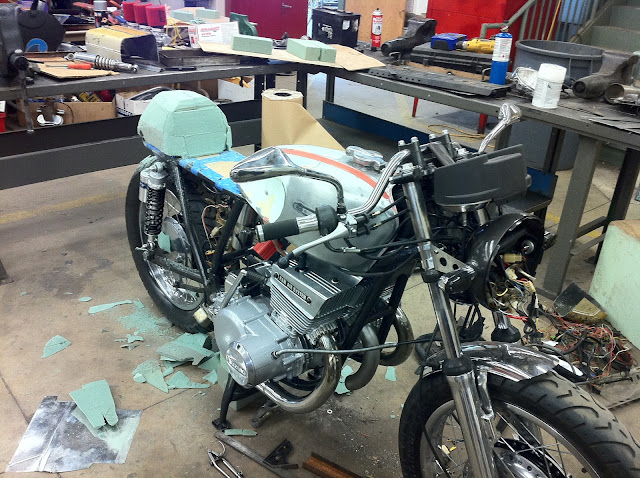
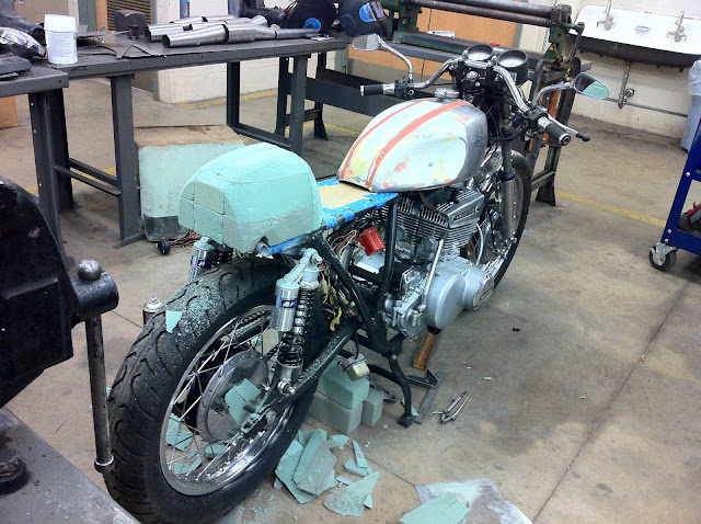
Here the kids are getting the frame ready to start making the tail section.
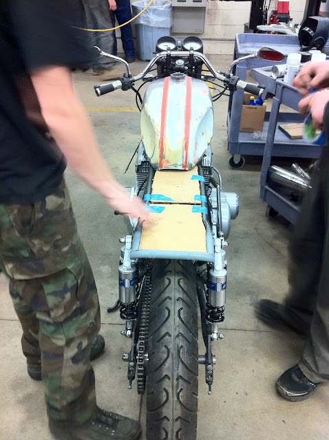
Couple things you may note from this picture:
New shocks are on
Tank is still not done (and only laying on frame (not straight either))
Installed mirrors
Still using the OE handlebars, upside down & backwards. Deal with it.
Seat/tail creation his week & these:
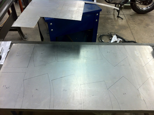
Whatcha think they are???
(I took the measurements from this site (http://www.caferacer.net/forum/topic.asp?TOPIC_ID=16266) and adapted them to 20ga, fed the measurements into this program: Pulse Rate's "Cone Layout" (http://www.pulserate.com/index.php?content=product" onclick="window.open(this.href);return false;" onclick="window.open(this.href);return false;" onclick="window.open(this.href);return false;). Which prints them out across 1-4 pieces of paper, which then were aligned together, cut out, and traced onto the sheet metal. Which will then be cut out, rolled on a slip roller & welded (by yours truly), then most likely cut apart, angled/clocked to fit the bike, rewelded, and installed.
(The down pipes from the OE setup will be used and 2" OD pipe tail sections (from a 10' stick at NAPA for $23 -cant go wrong with that price!) rather than rolling 2"x13" tubes from the sheet metal. The sheet metal was only $10.
The carbs were rejetted by my Russian (+2 on the main jets, +1 on the pilots) (thanks Coyote!)(+2 on the pilots available if needed).

Well, the cap had a loop on the top that 1) interferred w/ any seat pan that'd be made, 2) Didn't breathe or allow air into the tank (and allow oil out respectively) & 3) looked like a drink bottle cap.
So we took the cap over to the belt sander and removed the loop. When doing, so, we found the casting of the plastic was such that there were holes in the portion removed. Yes, it allowed air into the tank, but it also didn't look that great.
So I was thinking.... needs some sort of emblem for the top, 1) to cover the holes visually, and 2.)make it look better:
I began looking around through the extra parts I had from the project and saw the "S" Suzuki symbol on the mirror.
I thought, if I could just cut that out, it just might make a perfect fix!
So back to the sander it went:
I had measured the desired size circle that would fit on the cap, found the center of the "S" and using that made circle around the "S" to cut to.
The "S" removed from the mirror assembly:
In order to allow air to enter into the container (and allow oil out), a drilled in the center of the cap.
Then a hacksaw blade was used to slot the cap over the hole, so when the emblem was attached, air could travel down the slot, to the hole, under the cap.
Here it is finished:
Mirrors were purchased and installed (students had to drill & tap grips out from 8mm x 1.25 to 10mm x 1.25 -practical application of drill/tap chart and application of skills to correctly complete)
Here's a quick couple shots of that starting with a picture taken after one step (of two) drill bits sizes:
Tapping out to 10mm x 1.25:
The shocks that were on the "to get" list were also purchased.
While the original ones are in decent shape, they are corroded and too hard to clean/polish without taking them apart (don't know how they come apart). So they're back in storage:
Last I posted, I was exploring the possibility of making a seat bump/tail from a set of old hard side bags that came with the '72. I had cut them down and even gone to fiber glassing the pieces together but the result didn't flow with the shape of the tank & frame, so it was set aside. I had originally thought I was going to have to mold and glass a seat & bump and was hoping to get around that, but oh well. :O)
I have looked through a LOT of DIY pages on making tails/seats:
For instance: http://www.cafematty.com/making-a-cafe-racer-seat/ and will be doing such.
Here the kids are getting the frame ready to start making the tail section.
Couple things you may note from this picture:
New shocks are on
Tank is still not done (and only laying on frame (not straight either))
Installed mirrors
Still using the OE handlebars, upside down & backwards. Deal with it.
Seat/tail creation his week & these:
Whatcha think they are???
(I took the measurements from this site (http://www.caferacer.net/forum/topic.asp?TOPIC_ID=16266) and adapted them to 20ga, fed the measurements into this program: Pulse Rate's "Cone Layout" (http://www.pulserate.com/index.php?content=product" onclick="window.open(this.href);return false;" onclick="window.open(this.href);return false;" onclick="window.open(this.href);return false;). Which prints them out across 1-4 pieces of paper, which then were aligned together, cut out, and traced onto the sheet metal. Which will then be cut out, rolled on a slip roller & welded (by yours truly), then most likely cut apart, angled/clocked to fit the bike, rewelded, and installed.
(The down pipes from the OE setup will be used and 2" OD pipe tail sections (from a 10' stick at NAPA for $23 -cant go wrong with that price!) rather than rolling 2"x13" tubes from the sheet metal. The sheet metal was only $10.
The carbs were rejetted by my Russian (+2 on the main jets, +1 on the pilots) (thanks Coyote!)(+2 on the pilots available if needed).
-
imquattro
- To the on ramp
- Posts: 239
- Joined: Tue Jul 19, 2011 9:26 pm
- Country: USA
- Suzuki 2-Strokes: 72/74 GT550
- Location: Muncy PA
Re: GT550 Cafe project
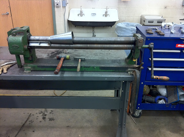
Started working with the slip roller this week.
After cutting out the parts from the sheet metal, and I've got to say, the Harbor Freight electric sheet metal shears work super slick! I took a botched cut cone and practiced with it on the slip roller.
Rolling a tube is simple.
Rolling a cone -no so simple.
First thought was to just roll it through -but that turns into a curly tube.
After some research, (and a DUH moment), I learned/realized that the cone, which is made up of a long end & short end, has to go through the rollers at different speeds -depending upon which end you're referring to. In other words, the shorter or narrower end has to travel through the rollers slower than the longer larger end. Easy to say, difficult to accomplish w/o some tooling.
In my search I found a simple device that acts as a brake for the narrow end of the cone -which allows the longer end to go through the rollers faster. A piece of 1"x1" angle iron about 6" long has a hole drilled in the middle of it. A nut on the end of a wire is fed through the hole w/ the nut being captured in the groove of the angle iron and the wire is fed through the slip roller and held taught by any means devised. One end of the angle iron is filled and welded. The wire is fed through the slip roller and with the blocked end of the angle facing towards the material. The small end of the soon-to-be-cone is placed up against the blocked end of the angle iron and the rollers pull the sheet metal through the rollers.
Here are the results:
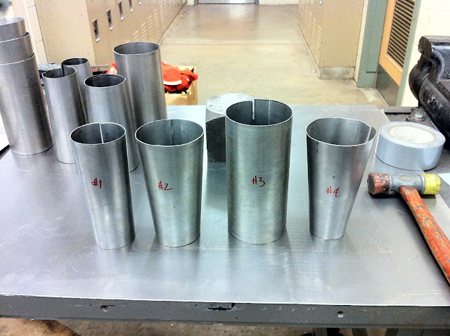
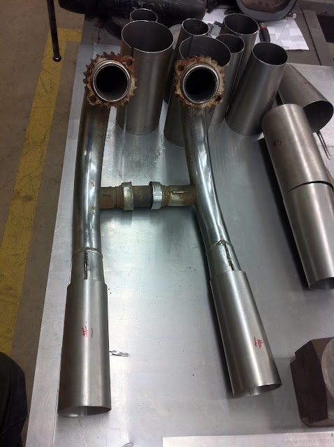
Here they are in order (missing down pipe & tail pipe):
Since I'm using the factory downpipes, I have to cross the point of no-return sometime.
Today's the day:
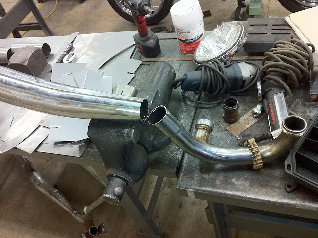
The picture makes them look better than they are. There scratched/dented and rusty AND HEAVY!
All the sheet metal to make the cones weighed less than ONE muffler!
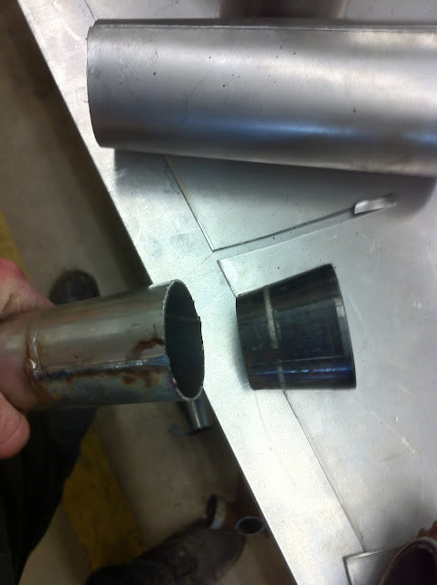
I cut about 2.5" after the stamped/welded portion begins because it flares out to the size of the inlet on the first cone there. The stamped portions will have to be ground down to allow the first cone to slip over the end.
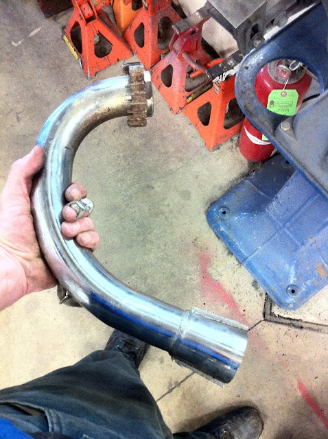
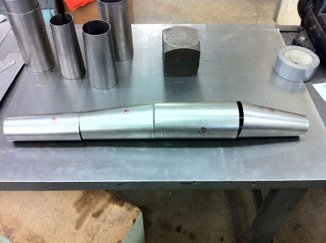
Here it is after grinding a bit of the metal away:
Fit's a bit loose (first cone's not welded so there's a gap in that, plus the down pipe needs opened up too)
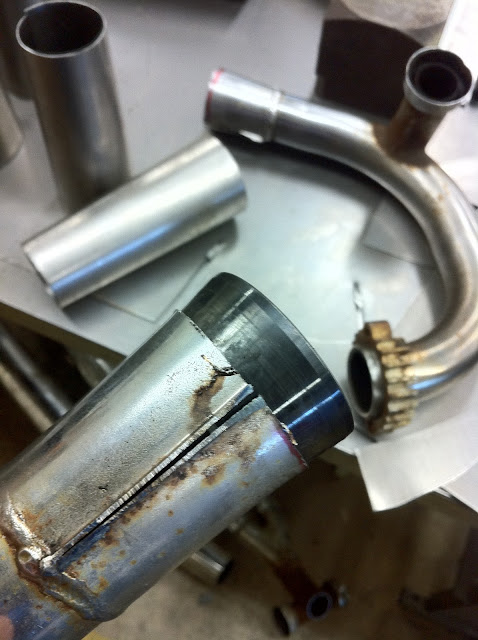
Lost a cylinder!
To open up the seams on the downpipe I borrowed a cone from our tire balancer and tapped it into the DP w/ a plastic hammer.
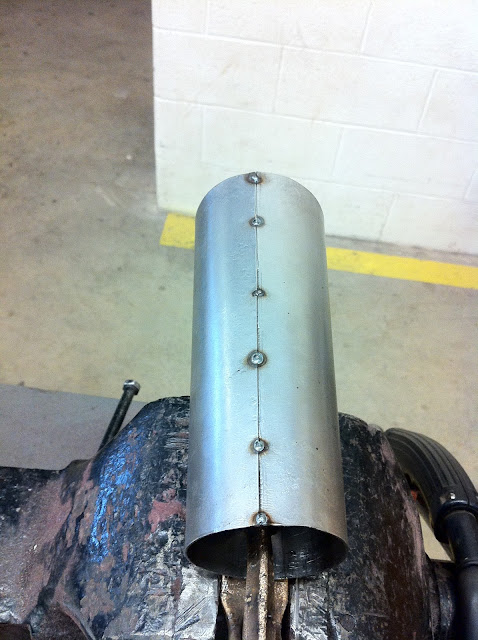
Time to weld up cone #1:
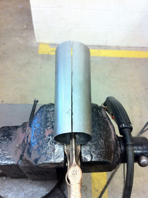
Starting in the middle, while be held together, the cone is tacked. Then the ends, and a couple in between. This helps eliminate warpage due to heating/cooling.
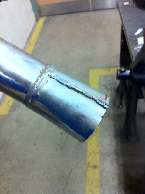
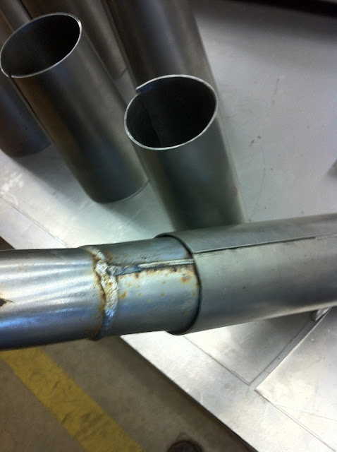
Here it is after being welded and after a blender pad:
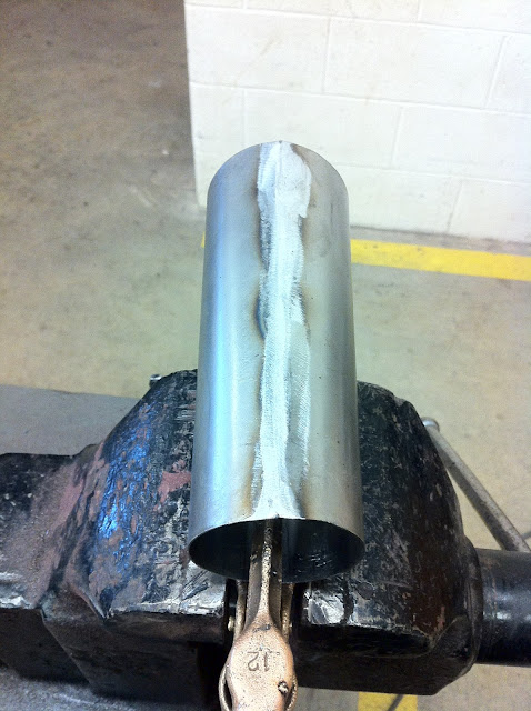
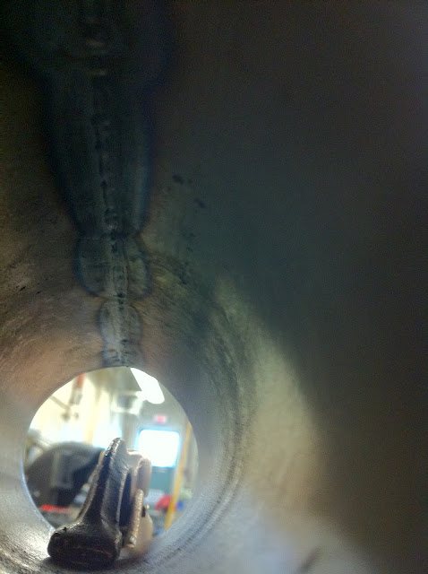
You can see the weld has nice penetration with minimal sugaring, even without purge gassing:
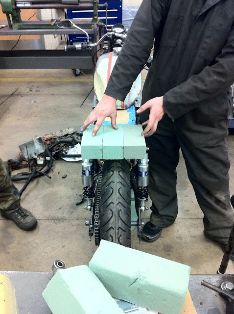
Students are also beinging to block out the tail portion for shaping a seat bump.
After cutting out the parts from the sheet metal, and I've got to say, the Harbor Freight electric sheet metal shears work super slick! I took a botched cut cone and practiced with it on the slip roller.
Rolling a tube is simple.
Rolling a cone -no so simple.
First thought was to just roll it through -but that turns into a curly tube.
After some research, (and a DUH moment), I learned/realized that the cone, which is made up of a long end & short end, has to go through the rollers at different speeds -depending upon which end you're referring to. In other words, the shorter or narrower end has to travel through the rollers slower than the longer larger end. Easy to say, difficult to accomplish w/o some tooling.
In my search I found a simple device that acts as a brake for the narrow end of the cone -which allows the longer end to go through the rollers faster. A piece of 1"x1" angle iron about 6" long has a hole drilled in the middle of it. A nut on the end of a wire is fed through the hole w/ the nut being captured in the groove of the angle iron and the wire is fed through the slip roller and held taught by any means devised. One end of the angle iron is filled and welded. The wire is fed through the slip roller and with the blocked end of the angle facing towards the material. The small end of the soon-to-be-cone is placed up against the blocked end of the angle iron and the rollers pull the sheet metal through the rollers.
Here are the results:
Here they are in order (missing down pipe & tail pipe):
Since I'm using the factory downpipes, I have to cross the point of no-return sometime.
Today's the day:
The picture makes them look better than they are. There scratched/dented and rusty AND HEAVY!
All the sheet metal to make the cones weighed less than ONE muffler!
I cut about 2.5" after the stamped/welded portion begins because it flares out to the size of the inlet on the first cone there. The stamped portions will have to be ground down to allow the first cone to slip over the end.
Here it is after grinding a bit of the metal away:
Fit's a bit loose (first cone's not welded so there's a gap in that, plus the down pipe needs opened up too)
Lost a cylinder!
To open up the seams on the downpipe I borrowed a cone from our tire balancer and tapped it into the DP w/ a plastic hammer.
Time to weld up cone #1:
Starting in the middle, while be held together, the cone is tacked. Then the ends, and a couple in between. This helps eliminate warpage due to heating/cooling.
Here it is after being welded and after a blender pad:
You can see the weld has nice penetration with minimal sugaring, even without purge gassing:
Students are also beinging to block out the tail portion for shaping a seat bump.
-
oldjapanesebikes

- Moto GP
- Posts: 3229
- Joined: Sat Feb 07, 2009 12:43 am
- Country: Canada
- Suzuki 2-Strokes: GT750(Jx3,L,M,A,B),T500
- Location: Ontario
- Contact:
Re: GT550 Cafe project
Ouchimquattro wrote:So I was thinking.... needs some sort of emblem for the top, 1) to cover the holes visually, and 2.)make it look better:
I began looking around through the extra parts I had from the project and saw the "S" Suzuki symbol on the mirror.
Ian
If at first you don't succeed, just get a bigger hammer !
If at first you don't succeed, just get a bigger hammer !
-
imquattro
- To the on ramp
- Posts: 239
- Joined: Tue Jul 19, 2011 9:26 pm
- Country: USA
- Suzuki 2-Strokes: 72/74 GT550
- Location: Muncy PA
Re: GT550 Cafe project
The stem was rusted like a cinamon sugar donut and I wasn't going to ever use them.
Oh well.
-
r3tro74
- On the main road
- Posts: 131
- Joined: Wed Feb 08, 2012 10:25 am
- Country: USA
- Suzuki 2-Strokes: 74 GT550
- Location: Michigan
Re: GT550 Cafe project
Building your own exhaust system and constructing a custom seat seem to be quite the projects. I think you are doing a GREAT job of using what you already have to build a one of a kind machine.
It might be a good idea to have some level indication on the oil tank. Maybee a "Gauge Glass" made from a pair of 90 degree barb fittings and a peice of clear Tygon tube.
It might be a good idea to have some level indication on the oil tank. Maybee a "Gauge Glass" made from a pair of 90 degree barb fittings and a peice of clear Tygon tube.
You do not have the required permissions to view the files attached to this post.
1974 Suzuki GT550
1983 Honda XL250
2002 Yamaha Bear Tracker
1959 Lone Star Malibu
1983 Honda XL250
2002 Yamaha Bear Tracker
1959 Lone Star Malibu
-
imquattro
- To the on ramp
- Posts: 239
- Joined: Tue Jul 19, 2011 9:26 pm
- Country: USA
- Suzuki 2-Strokes: 72/74 GT550
- Location: Muncy PA
Re: GT550 Cafe project
Thanks for the suggestion. I looked at a LOT of oil tanks, coolant tanks, catch cans, etc and understand the purpose behind the sight glass.
I personally don't like the look of them.
I'm the kind of guy that checks the fluids regularly and if a quart of oil will last 3+ tankfuls of fuel, when I'm checking every ride, I'm good.
I personally don't like the look of them.
I'm the kind of guy that checks the fluids regularly and if a quart of oil will last 3+ tankfuls of fuel, when I'm checking every ride, I'm good.
-
Coyote
- Moto GP
- Posts: 3404
- Joined: Tue Oct 21, 2008 2:41 pm
- Country: USA
- Suzuki 2-Strokes: GT550x2, GT750, GS1000
- Location: Tulsa, Oklahoma
Re: GT550 Cafe project
What? It's Friday. No updates?? What's the projected date for firing this puppy up? What are you going to do about the OEM cross overs on the exhaust?
Do yourself a favor and manufacture those pipes to retain the center stand. Bikes with no center stand -well - suck. A stand is necessary for chain adjustment, wheel alignment and sprocket alignment. My bike does not retain the center stand. However I was able to create one that pivots on the two OEM stand tubes. It's crude and poorly welded, but it does work.
Need a pic?
I was born with nothing and still have most of it left.
.
1978 GS1000C
1976 GT550 ongoing money pit.
.
1978 GS1000C
1976 GT550 ongoing money pit.
-
imquattro
- To the on ramp
- Posts: 239
- Joined: Tue Jul 19, 2011 9:26 pm
- Country: USA
- Suzuki 2-Strokes: 72/74 GT550
- Location: Muncy PA
Re: GT550 Cafe project
Funny you should mention that...Coyote wrote:What? It's Friday. No updates?? What's the projected date for firing this puppy up? What are you going to do about the OEM cross overs on the exhaust?
I was working on the updates. Having a yard sale tomorrow, so I've been busy.
No, I'm DEFINITELY NOT keeping the crossovers!
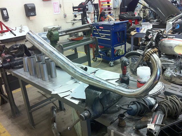
Did yesterday what I've been wanting to do since I bought the bike(s).
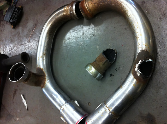
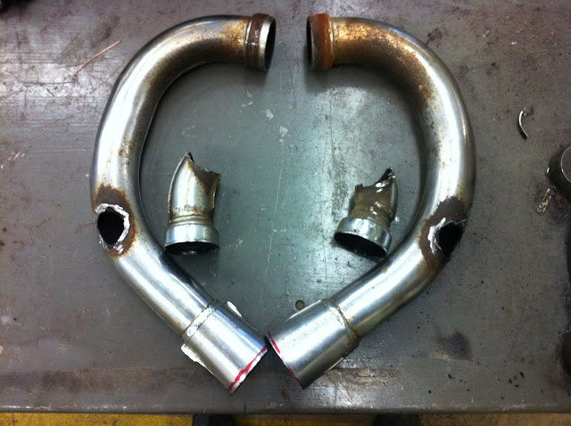
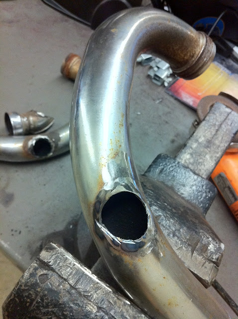
Then I cleaned up the hole:
Cut out a piece of sheet metal to fit, shaped it in the slip rollers:
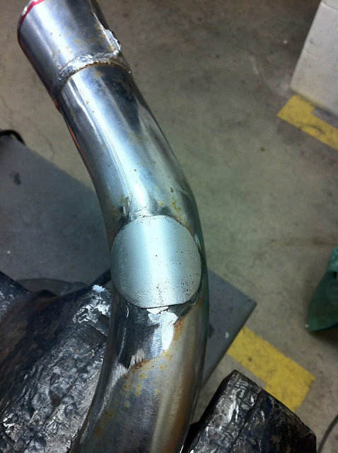
And tacked it into place:
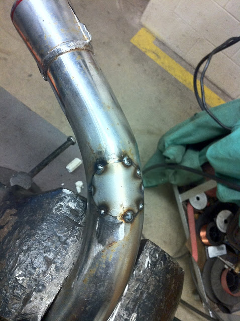
Then welded it:
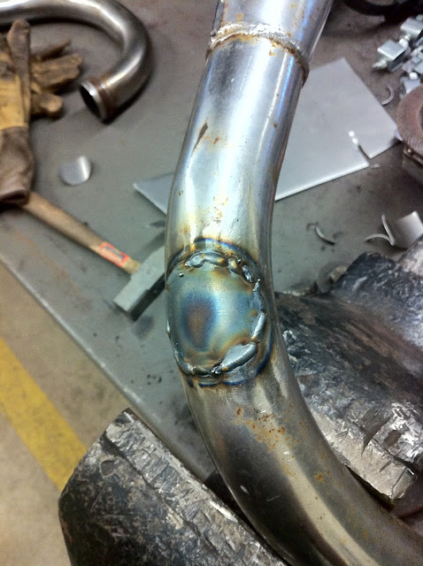
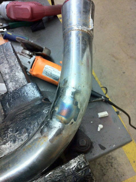
Here it is all cleaned up:
Spent about 5 minutes on the rear bump:
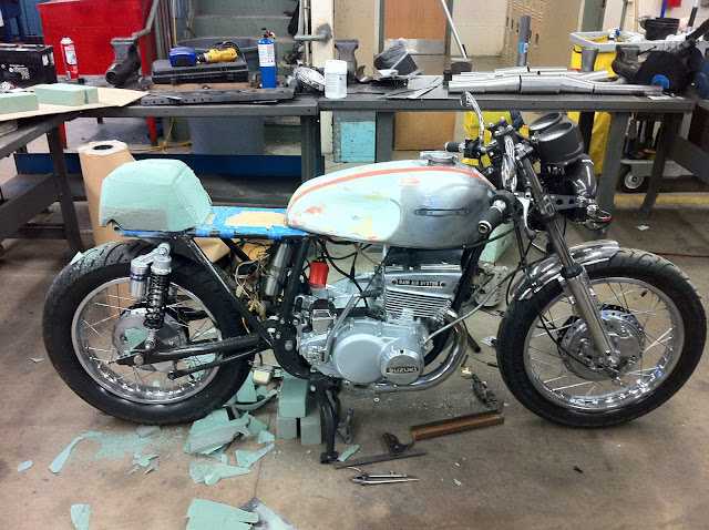
I agree, I sure hope I can. Not much room above it, but I like your idea of making extensions for it's hinge point.Coyote wrote:Keeping the center stand?
I saw once, on an older bike (30's/40's?) where the center stand swung up behind the rear wheel and towards the tail light... ?
Yes please?Coyote wrote:Need a pic?
Also, could someone measure their Jemco pipes? I need a distance from the exhaust gasket to the first transition(cone).
TIA!