I had a horrible feeling that would be the case. So back to the Pros and Cons.
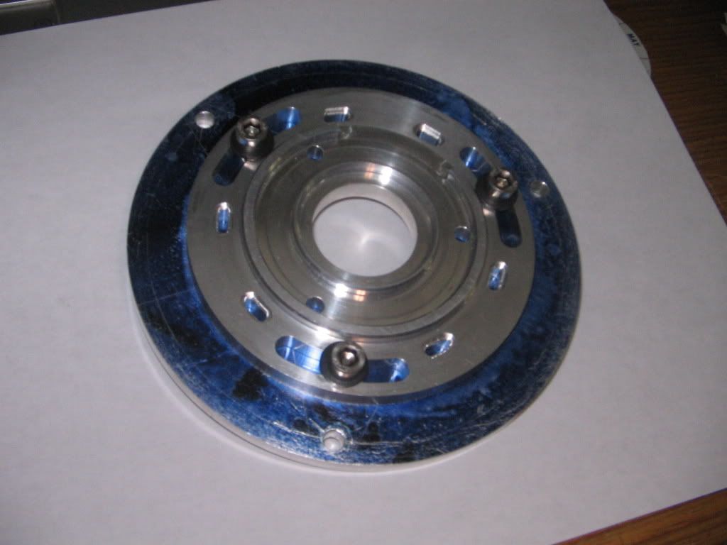
For the modified stock set up, how would the stator plate mount up? Does it need the same adapter plate but fitted to shortened standoffs that the alternator used?
If it needs an adapter plate, do you still have enough height on the flywheel?
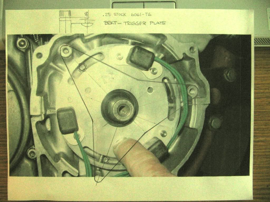
For the triggers outside design, you could probably make elongated slots in the adapter plate to make timing adjustment simpler/quicker. If that appeals to you, you might want to look at making it fit the recess that the alternator sits in, though that will not be easy with teh standoff placement.
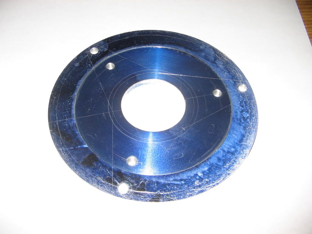
It should also be possible to make the ring for the flywheel as a press fit and not bother welding it to the machined down flywheel.
These are exactly the issues that Suzukidave and I have been working through with trying to adapt Polaris ignitions. Fortunately for dave, the ignition he chose is small enough to fit. I, on the other hand, went with a more recent ignition with TPS and other connections and of course, it's larger and won't fit.

What was wrong with those Suzuki engineers? Didn't they realize that we would be trying to adapt 21st century technology to these motors almost 40 years after the bike was designed!
 [/img]
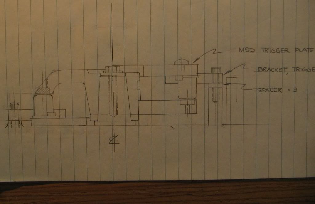


