If the fit is close but not exact, You can had fit it using valve grinding compound and working it back an forth like lapping a vlave. That is how all the clutch assemblies are fitted on Kt100 Yamaha Race Kart motors, and they are turning in excess of 15Grand every time the get on the track.
Wayne
Archived Posts
Moderators: oldjapanesebikes, H2RICK, diamondj, Suzsmokeyallan
-
Admin
- Supreme UFOB
- Posts: 34711
- Joined: Wed Dec 31, 1969 6:00 pm
Arctic Cat Flywheel fitup
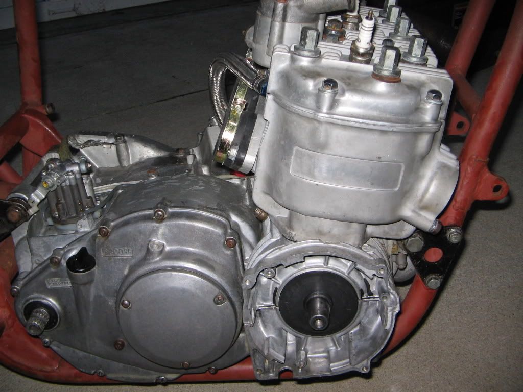
I'm a little concerned that the flywheel will take up all the available room in the housing. Until I can get back over to the shop and fit it up, I can only estimate based on this picture. Here is a view of the end of the crank. I'm not sure how much is left between the flyweel and crank seal once its on. Those MSD triggers are kinda tall.
-
Admin
- Supreme UFOB
- Posts: 34711
- Joined: Wed Dec 31, 1969 6:00 pm
MSD Ignition Initial Fit-Up
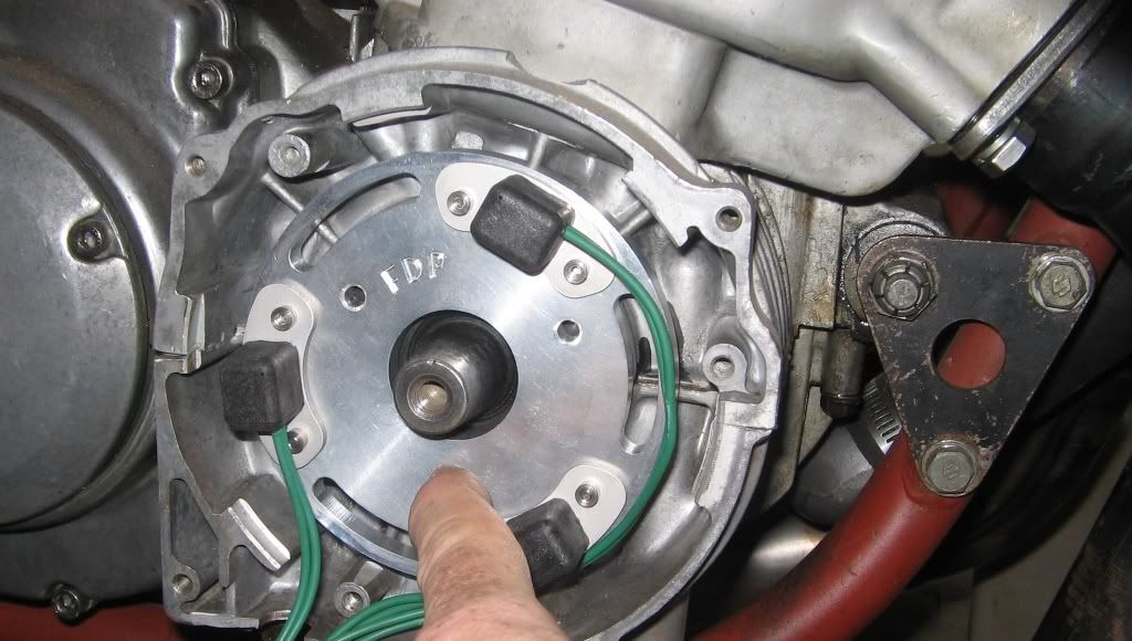
Pictures of the initial fitup of the MSD Arctic Cat Total Loss System.
The taper on the MSD flywheel matched the GT crank perfectly. The triggers and timing plate are a nice fit too. Unfortunately, there is not enough room to locate the triggers under the flywheel withouth machining down to both.
The taper on the MSD flywheel matched the GT crank perfectly. The triggers and timing plate are a nice fit too. Unfortunately, there is not enough room to locate the triggers under the flywheel withouth machining down to both.
-
Admin
- Supreme UFOB
- Posts: 34711
- Joined: Wed Dec 31, 1969 6:00 pm
-
Admin
- Supreme UFOB
- Posts: 34711
- Joined: Wed Dec 31, 1969 6:00 pm
Packaging the MSD
Even if I machined the trigger plate down to 3mm, moved the magnet up as high as possible within the flywheel and removed the excess material, I cant clear the triggers. I even thought about milling some square holes in the trigger plate and mounting the triggers through from the backside.
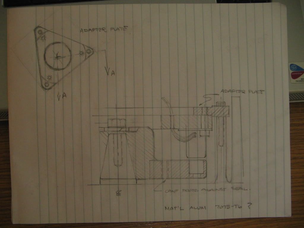
Here is a very rough conceptual hand sketch: The advantages of this configuration allow for much better access to the individual triggers for adjustment and keeps the flywheel as close to the case as possible. The trigger wires will route thru the holes in the plate and minimize the risk that they will come in contact with the rotatiing flywheel.
I'll use the MSD Flywheel and cut it down to keep the hub, then fab a disc that will get welded to the hub and machine finished.
The adapter for the trigger plate will look like the one in the drawing and will accept the existing alternator mounting lugs without having to cut them down or remove any material from the cases for that matter.
-
Admin
- Supreme UFOB
- Posts: 34711
- Joined: Wed Dec 31, 1969 6:00 pm
-
Admin
- Supreme UFOB
- Posts: 34711
- Joined: Wed Dec 31, 1969 6:00 pm
The Old Inside Out Job
TZ,
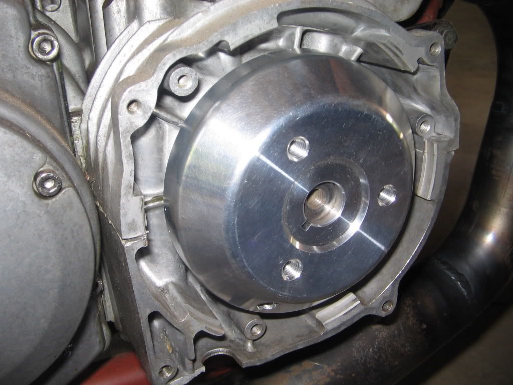
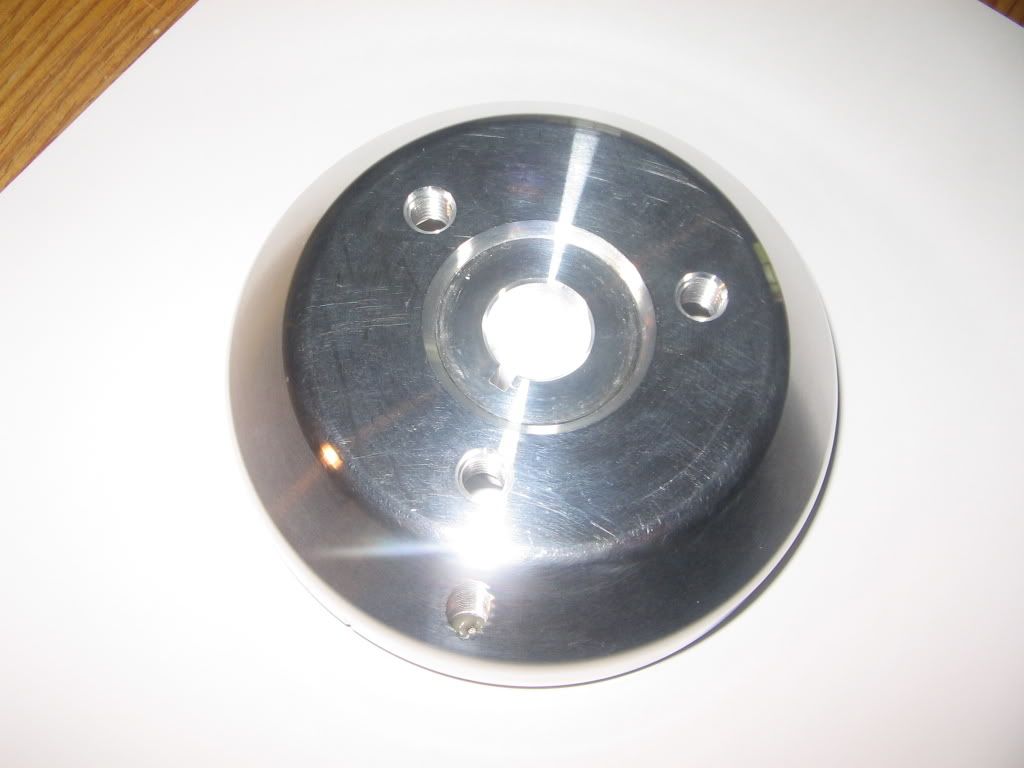
Its very close dimensionally to have the flywheel on the outside and clear the triggers but it may be possible. On the flywheel image below, you can see the "lone" tapped hole where the permanent magnet sits. We can raise the lower surface of the permanent magnet up to the spot where the tapped hole breaks through the flywheel. (The magnet measures .125" thick). Most of the magnet will be secure but a small portion will be exposed outside of the flywheel. Shouldnt be a problem.
From the base of the flywheel to the magnet will measure 20-21mm. I'll have to remeasure the trigger height again but I think it is close to the same. You may be right that we can sneak them in under the flywheel.
Then I just have to find a good way to secure the trigger plate up against the crank housing.
-
Admin
- Supreme UFOB
- Posts: 34711
- Joined: Wed Dec 31, 1969 6:00 pm
Cross Section of MSD Flywheel
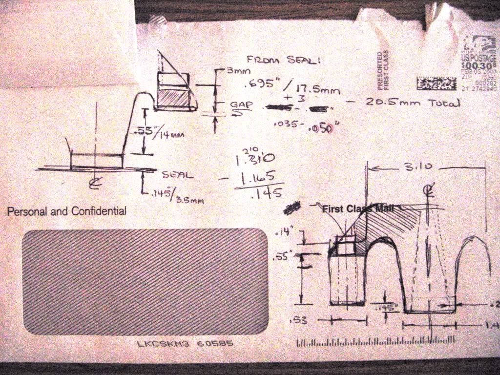
Here is the cross sectional sketch of the flywheel. I show the magnet pushed up as high as it can go to get to the 21-22mm dim. I think it might be a better approach to keep the flywheel in one piece and remove the excess material once we move the magnet up.
thanks for the comments about the sketches. they are certainly not to scale so there is still plenty of room for error.
thanks for the comments about the sketches. they are certainly not to scale so there is still plenty of room for error.
-
Admin
- Supreme UFOB
- Posts: 34711
- Joined: Wed Dec 31, 1969 6:00 pm
Sorry had to comment
Im a rank dumb Thumb shade tree Mech. and I am in love with the work your doin. thanks for the updates on your progress. Please Please, get a video of your first RUN!!!!! and post???
-
Admin
- Supreme UFOB
- Posts: 34711
- Joined: Wed Dec 31, 1969 6:00 pm
Thanks Dofin...I had it running several times back in August and September with that home-made 3-1 pipe. I swear you could have heard it on the other side of town. I have wanted to build this bike for a long - long time. Cant wait to finish the MSD install and crank it up again. I will make sure I get some video and post it.
Here is another conceptual sketch based on TZ's input...
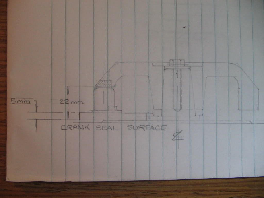
Here is another conceptual sketch based on TZ's input...
-
Admin
- Supreme UFOB
- Posts: 34711
- Joined: Wed Dec 31, 1969 6:00 pm
kevin, It's probably a perspective thing, but it looks almost as if the magnet has insufficient metal around it when it's that far out from the crank.
If you go back to your original idea for a moment, with the trigger plate on the outside, is there enough metal in the flywheel to cut it down and have the magnet close to the seal?
Your first design had a new plate welded or pressed onto the machined flywheel, and it looked as if the flywheel was pretty solid. The later design makes it look like the flywheel is almost hollowed out and I can't tell from the photos how much metal there is to play with.
Could you create that original design out of the original flywheel without resorting to an extra plate to hold the magnet?
When I try to draw it out, it looks as if it would machine through to the inner space before I have sufficient clearance to miss the trigger coils.